


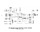

CIRCUIT DESCRIPTION
REMOTE
RECEIVER
and
CONTROL
LOGIC
AUDIO LINE
LEVEL INPUT
SELECTOR
SYSTEM
JFET BUFFER
AND RECORD
OUTPUT DRIVER
VIDEO
SWITCHING
TAPE MONlTOR
SWITCHING
LINE AMPLIFIER
TONE CONTROL
SYSTEM
MUTING SYSTEM
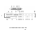
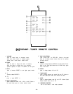
The Remote Receiver circuitry decodes the infrared pulses received from the Remote Control via the
front panel Infrared Receiver. This decoded information is sent to the Control Logic, which controls all
internal signal routing and Front Panel indicators. The Control Logic also receives input commands from
the Front Panel buttons.
The Control Logic creates digital codes fed to a CMOS-FET electronic selector switch. This arrangement,
besides allowing convenient remote operation, eliminates signal degradation due to mechanical switch
contacts, and allows the electronic switches to be located close to the’rear panel inputs for minimum
signal path lengths and reduced interchannel crosstalk.
The output of the audio Selector System is followed by a very high input-impedance JFET buffer pair
to establish negligible CMOS switch loading (for low distortion) and to provide a low-impedance source
for the Tape Outputs and the Volume and Balance controls.
The Control Logic creates digital codes fed to a CMOS-FET electronic selector switch. These inputs are
selected simultaneously with the corresponding audio inputs. The selected video input is fed through
separate wide bandwidth +6
dB
amplifiers for each of the Video Monitor and Video Record Outputs.
Only Video 1 and Video 2 signals are available at both the Video Monitor and Record Outputs. Video
3 is blocked from the Video Record Output to prevent feedback from occurring.
The Tape Monitor buttons drive CMOS-FETelectronic switches to break the line input path to insert tape
input signals. This switching arrangement allows optimum signal routing by placing the switches close
to the Tape Input jacks and the Input Selector System.
The 945 Line Amplifier is a Class-A JFET design employing a differential input stage, driving a
complementary high gain output stage, symmetrically driven for balanced slew-rate and low harmonic
distortion. This topology uses only four active devices per channel and extremely short loop feedback,
yielding high bandwidth and excellent stability.
The feedback loop contains two user selectable paths: one conventional path for flat response, and
another path allowing insertion of a tone control network. This arrangement allows maximally flat
response and the shortest, cleanest signal path when tone control action is not required.
The output of the Line Amplifier is capacitor coupled to the output of the preamplifier.
The Tone In/Out button allows complete removal of the tone controls from the signal path. This switching
is accomplished with the same type of CMOS-FET electronic switch used for the Input Selector. This
switching arrangement eliminates signal degradation due to mechanical switch contacts, and allows the
electronic switch to be located very close to the Line Amplifier circuitry.
The Bass Control is of a moving inflection, variable turnover type, and the Treble Control is of a shelving,
variable turnover type. These types of tone controls offer the best “tools” for modifying tonal balance
without introducing unwanted side effects. See Operation Section for further information.
The Muting System monitors the power supply voltage. During the power-up cycle, the Audio and
Headphone Outputs are muted until the regulated voltages reach a predetermined level, and then
remain muted for several seconds to allow all circuitry to stabilize. During power-down, or in cases of
excessively low AC line voltage, the Audio and Headphone Outputs are instantly muted to avoid
extraneous noises.
The muting is accomplished by grounding the Line Output jacks and disconnecting the output of the Line
Amplifier, using a relay with gold contacts.
-16-