


INSTALLATION
RACK-
MOUNTING
VENTILATION/
PLACEMENT
LINE
VOLTAGE
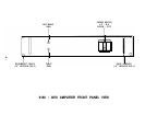
The 9180/9270 Amplifier is supplied in either a 17” Black Version, or a 19” Silver Version. The 19”
model has rackmounting holes provided for installation in equipment racks. The holes are on standard
EIA spacings.
Due to conflict with adjacent equipment, it may be advisable to remove the four rubber
feet from the bottom of the unit. The feet may be removed from the outside, with no dis-assembly of
the chassis necessary.
The 9180/9270 Amplifier can produce considerable heat during normal operation. The amplifier should
be placed on a hard, smooth surface to allow air to circulate beneath the unit. Additionally, allow at least
one inch of free space on either side, and several inches above and behind the amplifier to allow air
circulation around the heatsinks. This is particularly important when the unit is installed in a closed
cabinet.
In applications where the amplifier is driving low impedance and/or low efficiency loudspeakers at high
levels, thermal shutdown may occur if inadequate ventilation is provided. If this occurs, it may be
necessary to move the amplifier to a location with better free air circulation.
The amplifier should be located at least several inches away from sensitive components, (such as
preamplifiers, tuners, CD players, turntables, etc.) due to the possibility of audible hum or buzz from
magnetic radiation.
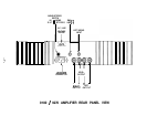
The 9180/9270 Amplifier is configurable for either 100, 120, 220 or 240 volt operation. This is
accomplished by moving the Voltage Selector on the printed circuit board. The procedure is detailed
in the section “CHANGING LINE VOLTAGE RATING”.
Make sure that the unit is configured for your local AC line voltage before attempted use. The
configuration is labelled directly above the power cord connector.
OPERATION/CONNECTIONS
POWER CORD
CONNECTION/
POWER SWITCH
INPUTS
Units wired for 100, 220 and 240 VAC are supplied without power cords. Local agents will supply cords
with male connectors appropriate to the local standard.
Units wired for
120
VAC are supplied with a detachable AC power cord. The female connector plugs
into the receptacle provided on the rear panel. This power cord is a standard IEC Type 320, 3-wire,
16 gauge assembly. Should replacement ever be necessary, be sure to replace it with an identical cord.
Never remove the grounding pin from the male end of the cord. In applications where a grounded outlet
is not available, a ground adaptor should be employed, with the ground tab or wire of the adaptor
connected to a suitable earth ground.
The AC power cord of the amplifier must be connected to a receptacle capable of delivering a minimum
of 1200 watts. The convenience outlets of some preamplifiers are not rated for this power level. Before
connecting the amplifier, be sure to check the rating of such outlets, and take into account the power
consumption of any other connected components to determine the total maximum power consumption.
If the amplifier is connected to a component with a switched convenience outlet, then the amplifier’s
Power Switch may be left ON at all times, and the power controlled by the switched outlet. If the amplifier
is connected to an
unswitched
outlet, then the amplifier’s power should be controlled by the front panel
Power Switch.
All input connections to the amplifier must be performed with the amplifier off!
The left and right audio inputs to the amplifier are via standard RCA jacks. In addition to the printed
labelling above the jacks, the channels are identified by RED for right channel, and WHITE for left
channel. Connect these jacks to the output of the preamplifier or other signal source.
When operating the amplifier in the Mono Mode, only the left channel input should be used.
-5-
IEC Type 320, 3-wire,