


CLEANING/
MAINTENANCE
It may be necessary to use additional adaptors on other grounded components if more than two
components are earth grounded. (In other words, only one earth ground per system should exist.)
Another potential source of multiple earth grounds is from coaxial antenna or cable service feeds
for FM or video sources, which usually are (and should be) earth grounded. The ground adaptor(s)
should cure this grounding problem as well.
WARNING: The use of ground adaptors (with the ground tab or wire of the adaptor
disconnected) will eliminate the safety feature of the grounded power cord. This safety
feature is intended to reduce the risk of electric shock should an internal fault in the
equipment result in an electrically “live” chassis. Therefore, this method of ground
isolation should be employed only when absolutely necessary, rather than as a general
practice. When using a ground adaptor for isolation, make sure that the power cord plug
is inserted into the receptacle in the same orientation as if no adaptor were present, to
maintain the same hot/neutral polarity.
SPECIAL NOTE ON VIDEO CABLE “GROUNDS”:
As mentioned above, the ground conductor
of cable service and antenna feeds should be connected to earth ground. Often, however, due to
long feed lengths, especially in apartment distribution systems, this ground will be of poor quality
and could be a source of noise. This interference is usually characterized by a high frequency
noise, rather than a hum or a buzz. If such interference is experienced, a separate earth ground
connection should be made from the cable outlet nearest the audio/video equipment to a known
good earth ground.
If ground loops exist due to potential differences in the interconnects in rack mounted systems, then
it is advisable to isolate the preamplifier chassis from the rack rails. This may be accomplished by
sandwiching a thin sheet of insulating material (i.e., plastic washers or several layers of electrical
tape, etc.) between the rack and the preamplifier, and securing the unit with non-metallic (i.e.,
nylon, etc.) hardware. It may be necessary to insulate other components so that only one
component is directly connected to the rack rails.
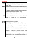
If the faceplate should become soiled, it may be cleaned with a slightly damp, soft cloth and, if
necessary, a mild detergent. Do not use any abrasive cleaners or solvents. Unplug the power cord
before attempting any cleaning operations.
Except as specifically detailed in the owners manual, there are no user serviceable parts or
adjustments inside the 9180/9270 Amplifier, and all servicing should be referred to qualified,
authorized personnel.
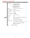
PARTS LIST
DESIGNATORS l- 99: LEFT CHANNEL
101-l 99:
RIGHT CHANNEL
201-299:
COMMON PARTS
301-399:
CHASSIS/POWER SUPPLY
DESIGNATOR VALUE PART NUMBER
ALL RESISTORS 114 WATT, 1% METAL FILM
(unless specified otherwise))
R1,R101
R2,R102
R3,R103
R4,R104
R5,R105
R6,R106
R7,R107
R8,R108
R9,R109
R10,R110
R11,R111
R12,R112
2.43K
2.43K
47.5
47.5
66.1
47.5
47.5
1K
1K
6.61K
47.5K
2.43K
RMP/4-2431
RMP/4-2431
RMP/4-0475
RMP/4-0475
RMP/4-0681
RMP/4-0475
RMP/4-0475
RMP/4-1001
RMPN-1001
RMP/4-6811
RMP/4-4752
RMP/4-2431
DESIGNATOR
R13,R113
R14,R114
R15,R115
R16,R116
R17,R117
R18,R118
R19,R119
R20,R120
R21 ,R121
R22,R122
R23,R123
R24,R124
R25,R125
R26,R126
R27,R127
R28,R128
R29,R129
R30,R130
R31 ,R131
R32,R132
VALUE
267 RMP/4-2670
267 RMP/4-2670
1K RMP/4-1001
1K
RMP/4-1001
100 RMP/4-1000
100 RMP/4-1000
47.5K RMP/4-4752
562 RMP/4-5620
475
RMP/4-4750
10 RMP/4-0100
47.5 RMP/4-0475
47.5
RMP/4-0475
221 RMP/4-2210
475 RMP/4-4750
475 RMP/4-4750
475 RMP/4-4750
221 RMP/4-2210
221 RMP/4-2210
221
RMP/4-2210
475K
RMP/4-4753
PART NUMBER
-12-
Parts List