


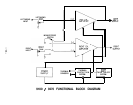

CIRCUIT HIGHLIGHTS
The input stage of the 9180/9270 Amplifier utilizes four low-noise, High-g, JFET’s (high transconductance
junction field-effect transistors), in a fully complimentary, symmetric configuration. This circuit configu-
ration results in excellent front-end headroom and a simple, straightforward connection to the
remainder of the circuitry. The ultra low noise characteristics of the JFET’s virtually eliminates noise
“mixing” (intermodulation) with the music signal, reducing discordant product frequencies known as
“noise grain”, or “noise fuzz”.
The input stage is cascode connected to convert the low voltage input system to the high voltage output
system, and “speeds up” the front end for superior bandwidth. The cascode stage is connected to an
emitter-follower and current mirror configuration that amplifies the current level about ten times,
necessary to drive the biasing string and final output stage driver emitter followers.
The final output stage uses multiple lateral MOSFET’s (Metal Oxide Semiconductor Field Effect
Transistors): four devices per channel in the 9180, and six per channel in the 9270. These devices,
unlike conventional bipolar transistors, have a negativetemperature coefficient, which means that they
do not exhibit “thermal runaway”. Thermal runaway is a phenomenon whereby a transistor heats up
as it conducts more current, which causes it to get hotter, and conduct more current, and so on, until
the device self destructs. Since MOSFET’s are inherently self-protecting, no sonically degrading,
complex circuitry is required to monitor and protect the output devices.
Furthermore, these lateral MOSFET’s exhibit a very linear input to output transfer function. Their
connection in circuits and operating characteristics are very similar to vacuum tubes, which is perhaps
responsible for their widely recognized sonic trait of being very “musical” and non-fatiguing.
Conversion to Mono Mode is accomplished by driving the negative input (feedback point) of the right
channel with the output of the left channel. This causes the right channel to mirror exactly the output
of the left channel, but 180 degrees out of phase. This creates twice the voltage swing to be available
across the two red output binding posts. This simple method of bridging the amplifier (involving only
one resistor) eliminates the costly and sonically degrading invertor circuitry used in other amplifiers.
The Thermal Protection System consists of thermistors (temperature sensitive resistors) mounted to
the heatsinks, connected to a comparator system that activates when the heatsinks reach an unsafe
operating temperature. The output of the comparator system is connected to a small MOSFET switch
that turns off the input stage of the amplifier, which effectively shuts down the entire amplifier. When
the heatsinks cool to a safe temperature, the amplifier is turned on again.
The Soft Turn On/Off System cooperates with the Thermal Protection System by sensing the high
voltage power supply. At power up, when both the comparator and power supply have stabilized to
normal operating levels, the Soft Turn On System activates the amplifier circuitry through the same
MOSFET switch in the input stage. At power down, the system deactivates the amplifier rapidly before
the power supply begins to collapse. This system eliminates spurious noises during the turn on/off
cycle.
The power supply utilizes a very large UI type transformer with dual multi-tapped primaries to allow
alternate connections for world-wide voltage operation. Selection of the various voltage options is
made via a simple multi-position plug inside the unit. The UI type of transformer construction results
in very low stray magnetic leakage.
The transformer feeds a conventional split full-wave bridge rectifier system.
Power supply capacitance
is 15,000
uF
per rail. Further power supply de-coupling is provided for the input stage of each channel.
-9-