


GENERAL
TROUBLESHOOTING
HINTS
GROUND
LOOPS
WARNING! UNPLUG THE UNIT FROM AC POWER BEFORE ATTEMPTING THIS PROCEDURE.
FAILURE TO DO SO CAN RESULT IN SEVERE ELECTRICAL SHOCK.
REQUIRED TEST EQUIPMENT: Milliammeter capable of measuring at least 300
mA.
1)
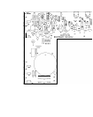
Remove the top cover by removing the seven allen head screws (three on each side, one at rear
center).
2)
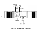
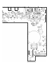
Using the diagram “Component Layout” as a guide, find the fuses labelled F1 and F2 for the left
channel, or F1 01 and F102 for the right channel.
3)
Working on one channel at a time, remove either one (and only one) of the fuses. Connect the
milliammeter to the two fuse clips, and set the meter to a scale capable of measuring at least 300
mA.
WARNING! THE NEXT STEP OF THIS PROCEDURE CAN EXPOSE THE OPERATOR TO
UNINSULATED HIGH VOLTAGES. KEEP ALL BODY PARTS CLEAR OF THE INTERNAL
CIRCUITRY OF THE AMPLIFIER.
4)
Apply power to the amplifier, and allow the unit to thermally stabilize for about three minutes. (If
using an analog meter, and the meter reads backwards, temporarily remove power and reverse
the meter leads.)
5)
Again referring to the diagram, locate the trimmer potentiometer labelled Pl for the left channel,
or P101 for the right channel. Using a small screwdriver, adjust the trimmer for a measured
current according to the following:
9180: 200
mA
9270: 300
mA
6)
Remove power from the amplifier. Wait about one minute for the power supply to discharge, and
remove the meter connections. Replace the fuse.
7)
Repeat steps #2,3, 4, 5 and 6 for the other channel.
8)
Replace the covers.
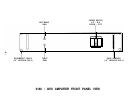
The 9180/9270 Amplifier contains five internal fuses: one for AC line power, and four for DC power
supplies. These fuses should not generally blow unless a malfunction has occurred. These fuses
should be replaced only by a qualified technician, and only with the exact type(s) and rating of fuse(s)
originally supplied. If a fuse is replaced and blows again within a short time, check all output
connections for short circuits, or abnormally low speaker load impedances.
If all connections and load
conditions appear to be correct, disconnect all power immediately and return for service.
If all controls, fuses, cables, etc. seem to be functioning properly, a process of one-at-a-time component
substitution should be employed until the defective unit is identified. If only one channel is not
functioning properly, a one-at-a-time reversal of interconnect and speaker cables from left to right
should reveal the malfunctioning component.
Ground loops are characterized by a low level hum or buzz in the system. Loops are caused by a
voltage potential difference between two points in a ground circuit, and aggravated when multiple paths
for a given circuit exist.
Noise-free audio performance is dependent upon all grounds being at the same
potential, with a single path for each ground connection. Ground loops can exist in two forms: 1) loops
created in audio interconnects, and 2) loops created between earth grounded chassis.
Mounting components to a rack with metallic rails may introduce ground loops between associated
equipment, because the rails can introduce a second ground path. The extent of this problem will
depend on the grounding arrangements of associated equipment. Ground loops can occur in non-
rackmounted equipment, though it is less common.
If ground loops occur, and any other component in the system has a three wire grounded power cord,
the first step should be to use a ground adaptor (with the ground tab or wire of the adaptor not
connected) on the power cord plug of the preamplifier.
DO NOT cut off the grounding pin on the plug!
-11-