


ADDITIONAL INFORMATION
LOUDSPEAKER
LOAD IMPEDANCE
CONSIDERATIONS
CHANGING
LINE
VOLTAGE RATING
ADJUSTlNG BIAS
The 9180/9270 Amplifier is suitable for use with a wide variety of loudspeaker types and load
impedances. Though not rated for impedances below 4 ohms, the amplifier is capable of driving
lower impedances. Operation at low impedances is limited by the thermal dissipation capacity of
the heatsinks and the airflow around the unit. Operation at very high power levels into low
impedances for extended periods may overheat the amplifier, but no damage will occur due to the
Thermal Protection System.
In the Mono Mode, some additional consideration is required when driving low impedances. When
a stereo amplifier is converted (bridged) into a single channel mono amplifier, each half of the
bridged amplifier “sees” only half of the loudspeaker’s load impedance. For example, when driving
an 8 ohm load in the Mono Mode, each channel is actually loaded to 4 ohms. Therefore, little
advantage is gained when attempting to drive 4 ohm loads (2 ohms per channel) in the Mono Mode,
because of the reduced power available at extremely low impedances.
It is usually better to use
a stereo amplifier of higher power rating (rather than two bridged amplifiers of lower power) when
driving low impedances.
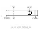
The 9180/9270 Amplifier is equipped with a simple means to adjust the AC line voltage rating for
100, 120, 220, or 240 volts AC, 50/60 Hz. The configuration is labelled above the power cord
connector. If the amplifier will be used in a location that requires a different line voltage, use the
following procedure to change the configuration.
Review the modification instructions before
attempting this procedure. If any doubts exist about one’s ability to change the line voltage, it is
advisable that the procedure be conducted by a qualified technician.
WARNING! UNPLUG THE UNIT FROM AC POWER BEFORE ATTEMPTING THIS PROCE-
DURE. FAILURE TO DO SO CAN RESULT IN SEVERE ELECTRICAL SHOCK.
1)
Remove the top cover by removing the seven allen head screws (three on each side, one at
rear center).
2)
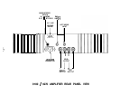
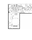
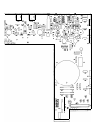
Using the diagram “Component Layout” as a guide, find the white Voltage Selector plug on
the printed circuit board located behind the front panel Power Switch. Note that this plug has
several alternate positions. Each position is labelled for where the end of the plug is to be
aligned for each appropriate voltage.
Move this plug to the new desired position, making sure
that the plug is fully seated on the mating pins.
3)
Depending upon which new voltage is chosen, it may be necessary to change the AC line
fuse. Locate the clip-mounted Line Fuse adjacent to the Voltage Selector plug. Replace the
fuse with a new slow-blow fuse as follows:
9180: 100 and 120 VAC: 7 amp
220 and 240 VAC: 4 amp
9270:
100 and 120 VAC: 10 amp
220 and 240 VAC: 5 amp
4)
Replace the cover.
5)
Obtain a new voltage configuration label from the factory, and affix over the original markings
on the rear panel. Alternately, prepare a small self-adhesive label and indicate the new
voltage with permanent ink. Relabelling the unit is a vital safety requirement, particularly if
the amplifier is sold to a new owner.
The 9180/9270 Amplifier employs a single control per channel to set the bias operating point of the
output stage. This bias point is factory set, and normally should not require adjustment for the life
of the product. However, should improper bias be suspected, or if repairs have been made that
would require a readjustment of bias, the following procedure should be used. Review the
instructions before attempting this procedure.
If any doubts exist about one’s ability to set the bias,
it is advisable that the procedure be conducted by a qualified technician.
-10-
slow-blow fuse