


GENERAL
TROUBLESHOOTING
HINTS
Place the preamplifier on a soft, protective surface. Remove the eight allen head screws (four
on each side), and six phillips head screws (three each on top and bottom), securing the top and
bottom covers. Remove covers.
2)
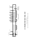
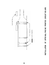
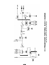
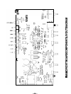
Referring to the diagram “Main Printed Circuit Board Component Layout”, locate the three wire
jumper locations labelled “A”, “B”, and "C", in front of the power transformer. These jumpers
control the series/parallel connections of the power transformer’s primary.
3)
Remove the old jumper(s) by desoldering and replace with new jumper(s) as indicated:
100
-
120 VAC: Jumpers A & B installed
200
-
240 VAC: Jumper C installed
Be sure to clip off excess wire length on the solder (non-component) side of the printed circuit
board.
4)
Referring again to the diagram, locate the clip-mounted fuse. Replace this fuse with a new slow-
blow fuse as indicated:
100
-
120 VAC:
1/10
AMP
200
-
240 VAC: 1 /16 AMP
5)
Referring again to the diagram, locate the wire jumper location labelled “Remove For 240
VAC”, behind the transformer. This jumper controls the voltage supplied to the Power Switch
indicator lamp. Remove or install this jumper as indicated:
100
-
120 VAC: Jumper Installed
200
-
240 VAC: Jumper Removed
6)
7)
Replace the covers.
Obtain a new voltage configuration label from the factory, and affix over the original markings.
Alternately, prepare a small self adhesive label and indicate the new voltage range with
permanent ink. Relabelling the unit is a vital safety requirement, particularly if the preamplifier
is sold to a new owner.
The 915 Preamplifier is configured for normal operation when all toggle switches are in the “down”
position. That is, Tape Monitor is NOT selected, Tone Controls are OFF, and the outputs are ON. If
no sound is heard from the system, first check the position of the Tape Monitor and Output switches.
If altered tonal balance is detected (even with the Bass and Treble controls centered), check the
position of the Tone switch.
If the Ready light is off or glowing red, the preamplifier’s outputs are muted and no sound will be heard.
If rated AC power is present and the light is glowing red, then the delay circuit will un-mute the outputs
within several seconds. If the delay circuit does not un-mute within a few seconds and the light
continues to glow red, check for low AC line voltage, and that the unit is configured for the local line
voltage. If the Ready light is off, check the AC power connections.
If all controls are in the intended position and the Ready light is green, check all system power
connections, interconnecting and speaker cables, and fuses. The 915 does contain one internal
power fuse, but this fuse should not generally blow unless a malfunction has occurred. This fuse
should be replaced only with the exact type and rating of fuse originally supplied. If this fuse is replaced
and blows again within a short time, disconnect all power immediately and return for service.
If all controls, fuses, cables, etc. seem to be functioning properly, a process of one-at-a-time
component substitution should be employed until the defective unit is identified. If only one channel
is not functioning properly, a one-at-a-time reversal of interconnect and speaker cables from left to
right should reveal the malfunctioning component.
-16-