


INSTALLING
CARTRIDGE LOADS
CHANGING UNE
VOLTAGE RATlNG
Optional cartridge loading is a “fine tuning” matter. Many cartridges are not sensitive to loading
and work well without it. Only a cartridge’s manufacturer can provide recommended loading, as
every cartridge is different. And only the user can say for sure whether or not it produces
meaningful sonic improvement.
Components suitable for cartridge loads may be obtained from electronic parts or specialty audio
component suppliers. Resistors should be 1% tolerance, metal-film,
l/4
watt types. Capacitors
should be axial lead, 10% (or better) tolerance, miniature polypropylene or polystyrene types.
As supplied from the factory, the 915 Preamplifier has been fitted with 100 ohm resistors and 220
pF capacitors installed in the appropriate sockets. While these values are suitable for most
cartridges, the procedure described below may be used to alter these values. Review the
installation instructions before attempting this procedure. If any doubts exist about one’s ability
to install the cartridge loads, it is advisable that the procedure be conducted by a qualified
technician.
WARNING!
UNPLUG THE UNIT FROM AC POWER BEFORE ATTEMPTING THIS PROCE-
DURE. FAILURE TO DO SO CAN RESULT IN SEVERE ELECTRICAL SHOCK AS WELL AS
DAMAGE TO THE PREAMPLIFIER AND/OR PHONO BOARD.
1)
Place the preamplifier on a soft, protective surface. Remove the four allen head screws (two
on each side), and three phillips head screws, securing the bottom cover. Remove cover.
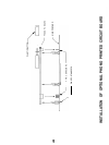
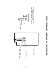
2)
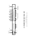
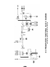
Refer to the diagram “Installation Of Optional Cartridge Loads” for the location of the
appropriate sockets, and how to form the component leads. Make sure that the component
leads are only long enough to securely mate to the sockets. Be sure not to stress the
component lead where it enters the body of the part. Observe carefully which sockets are
for MM (capacitors) and for MC (resistors).
3) Replace cover.
NOTE:
Even while experimenting with different optional loads, the cover must be replaced before
re-applying AC power, not only for safety reasons, but to shield hum and interference which can
totally invalidate any attempts at sonic evaluation.
CAUTION:
When low value resistors are installed and selected by the MC switch position,
accidentally using this setup for a high output moving coil cartridge can result in deceptively normal
output levels, but with improper cartridge frequency response.
The 915 Preamplifier can be internally wired for two different AC line voltage ranges: 100
-
120
VAC, or 200
-
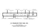
240 VAC, 50/60 Hz. The configuration is labelled above the power cord connector.
If the preamplifier will be used in a location that requires a different line voltage, it is possible to
change the configuration. Review the modification instructions before attempting this procedure.
If any doubts exist about one’s ability to change the line voltage, it is advisable that the procedure
be conducted by a qualified technician.
NOTE:
As supplied from the factory, units wired for 100-l 20 VAC have five Convenience Outlets,
and the Power Switch controls the Switched Convenience Outlets only. (Power is applied to the
preamplifier’s circuitry as soon as the unit is plugged in.) For units factory wired for 200-240 VAC,
no Convenience Outlets are supplied, and the Power Switch controls application of power to the
preamplifier’s circuitry. Note that changing the Line Voltage affects only the operating line voltage:
the above described switching arrangements will remain the same.
WARNING!
UNPLUG THE UNIT FROM AC POWER BEFORE ATTEMPTING THIS PROCE-
DURE. FAILURE TO DO SO CAN RESULT IN SEVERE ELECTRICAL SHOCK.
-14-
Resistors
Capacitors
100 ohm resistors
220