


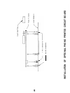
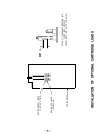

OUT 1, OUT 2
AND OUTPUT OFF
SWITCH
HEADPHONE
Activating this switch (UP position) turns off both Out 1 and Out 2. It does not affect the headphone
output. This control is useful for turning off the signal to the power amplifier(s) during headphone
listening, or for general system muting purposes.
When activated, the output switch disconnects the line amplifier from the output jacks, and grounds
the jacks to prevent possible system noise due to open amplifier inputs.
Out 1 and Out 2 are connected in parallel, to provide two equal outputs to amplifiers. This feature is
useful for bi-amplified speaker systems, or for running two amplifier/speaker systems.
A common system “malfunction” can often be traced to inadvertently leaving the Output Off Switch
engaged. In case of no sound from the speakers, check that the Output Switch is de-activated (DOWN
position).
The headphone receptacle is a standard
1/4”
stereo phone jack, with the tip of the plug as the left
channel, the ring the right channel, and the barrel ground.
The headphone driver circuit is separate from the main line amplifier, and therefore, driving
headphones will not cause distortion on the main outputs.
Unless simultaneously operating loudspeakers during headphone use, the Output Off Switch should
be used to disable the outputs. Remember to reduce the Volume Control setting before turning on the
outputs again, since a normal listening level for headphones may correspond to a surprisingly high
volume for loudspeakers.
CIRCUIT DESCRIPTION
PHONO SECTION
(When Installed)
LINE LEVEL
INPUT SELECTOR
SYSTEM
Each Phono channel consists of six low-noise JFET's connected in a complementary-symmetry, non-
differential configuration. Shorted-input moving coil equivalent-input noise measures about -137 dB
(140 nV) wide band.
Only two stages are used to yield an open-RIAA-loop gain of about 110 dB in moving coil mode and
90 dB in moving magnet mode. RIAA loop closure yields 58.5 dB and 38.5 dB respectively, at 1 kHz.
The first stage employs an active load technique in which the load JFET’s are connected as gyrators,
acting as if they were very large inductors. This arrangement allows very high gain at low frequencies
and a natural roll-off of high frequencies in the amplifier loop, before the RIAA negative feedback loop
is closed.
DC operating point stability is obtained by long time constant DC negative feedback applied from
output to intermediate points in the gain structure.
AC gain is set by the RIAA network feeding back output signals to the sources of the input JFET pair.
Switching to moving coil (MC) from moving magnet (MM) results in three operational changes: 1)
open-loop gain is increased by 20 dB, 2) closed-loop gain is increased by 20 dB, and 3) user adjustable
cartridge loading is changed from capacitive to resistive.
The phono outputs are capacitively connected to the high level Input Selector System.
The front panel rotary input Selector Switch creates digital codes fed to a CMOS-FET electronic
switch. This arrangement eliminates signal degradation due to mechanical switch contacts, and
allows the electronic switches to be located close to the rear panel inputs for minimum signal path
lengths and reduced interchannel crosstalk. The output of the Selector System is grounded between
positions of the rotary knob to minimize switching noise.
-lO-
OUTPUT