


GMA 240 Installation Manual Page v
190-00917-01 Revision A
LIST OF ILLUSTRATIONS
FIGURE PAGE
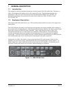
1-1 GMA 240 Unit View .........................................................................................................................1-1
2-1 GMA 240 Unit Rack (115-00262-00) ...............................................................................................2-4
3-1 Audio Shield Termination .................................................................................................................3-2
3-2 Access Hole Location (Top View) ....................................................................................................3-5
4-1 Backshell Rear Connector Plate.........................................................................................................4-1
4-2 Rear Connectors J2401 & J2402, Viewed from Back of Unit...........................................................4-1
A-1 GMA 240 Outline Drawing ..............................................................................................................A-1
A-2 GMA 240 Connector/Rack Assembly Drawing ...............................................................................A-3
A-3 GMA 240 Recommended Panel Cutout Dimensions .......................................................................A-5
B-1 GMA 240 Interconnect Drawing (page 1 of 3)................................................................................. B-1
B-1 GMA 240 Interconnect Drawing (page 2 of 3)................................................................................. B-3
B-1 GMA 240 Interconnect Drawing (page 3 of 3)................................................................................. B-5
B-2 GMA 240, J2401 & J2402 Connector Layout Drawing................................................................... B-7
C-1 GMA 240 Internal Configuration Jumper Layout Drawing ............................................................. C-1
LIST OF TABLES
TABLE PAGE
3-1 Recommended Crimp Tools ..............................................................................................................3-1
4-1 J2401 Pin Assignments......................................................................................................................4-2
4-2 J2402 Pin Assignments......................................................................................................................4-3