


GMA 240 Installation Manual Page 4-1
190-00917-01 Rev. A
4 SYSTEM INTERCONNECTS
4.1 Connector Description
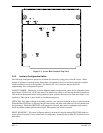
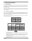
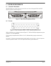
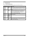
The GMA 240 has two 44-pin connectors located at the rear of the unit designated J2401 and J2402
which are oriented as shown in Figure 4-1.
J2401J2402
Figure 4-1. Rear View of Backplate and Rack
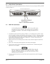
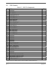
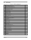
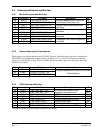
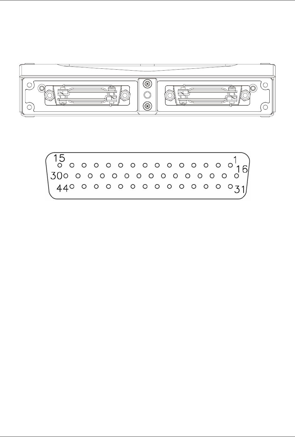
4.2 Pin List
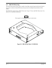
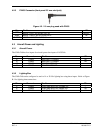
Figure 4-2. Rear Connectors J2401 & J2402, Viewed from Back of Unit
J2401 and J2402 pins are configured as shown in Figure 4-2. J2401 and J2402 pin assignments are given
in Tables 4-1, 4-2, and Appendix B.
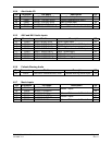
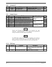
Following the pin assignment tables (Tables 4-1 & 4-2), additional tables group pin connections by
function.
An asterisk (*) following a signal name denotes that the signal is active low logic. Active low inputs are
connected to ground to activate. Active low outputs sink current to ground when active.