


GMA 240 Installation Manual Page 2-1
190-00917-01 Rev. A
2 INSTALLATION OVERVIEW
2.1 Introduction
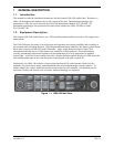
This section provides the necessary information for the installation and checkout of the GMA 240 Audio
Panel. Installation of the GMA 240 will differ according to equipment location and other factors.
Cabling will be fabricated by the installing agency to fit these various requirements. The appendices
contain interconnect wiring diagrams, mounting dimensions, and information pertaining to installation.
2.2 Installation Materials
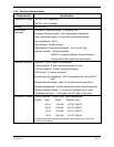
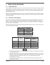
2.2.1 Equipment Available
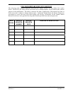
GMA 240 Audio Panel, Ship Level Assembly, P/N 010-00735-() includes the following, depending on
part number:
Item Garmin P/N
Connector Kit, GMA 340 011-00652-00
Rack Backplate, GMA 340 011-00678-00
Unit Assembly, GMA 240 011-01988-00
Audio Cables, 2.5 mm RA Stereo Plug 011-02079-00
Install Rack, GMA 340 115-00262-00
2.2.2 Additional Equipment Required
• Cables: The installer will fabricate and supply all system cables. Interconnect wiring diagrams
are detailed in Appendix B.
• Hardware: #6-32 100° flat head screw (6 ea.) and #6-32 self-locking nut (6 ea.). Hardware
required to mount the installation rack is not provided.
• Stereo headphone jacks (up to 4), microphone jacks (up to 4), 3.5mm stereo jacks (up to 2).
Insulating type jacks or insulating washers should be used for all jacks to isolate them from
aircraft chassis.
2.3 GMA 240 Wiring, Configuration, and Adjustment Options
The GMA 240 has several configuration/adjustment options, consideration of these options should be
discussed with the end user(s) of the aircraft before wiring begins. These configuration/adjustments are
described in the following sections:
• Wiring options – Sections 2.3.1 and 4.4.1
• Internal configuration jumpers - Section 2.3.1
• Volume/Mute adjustments - Section 2.3.2