


Page 3-2 GMA 240 Installation Manual
Rev. A 190-00917-01
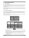
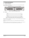
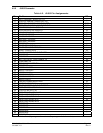
3.3 Audio Shield Termination
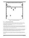
The audio shield wires should be terminated at the rear of the unit to the screws between J2401 and J2402
as shown in Figure 3-1.
Audio shields daisy chained and
terminated using a lug attached to
either of these screws.
Rear View of backplate and rack
J2401J2402
Figure 3-1. Audio Shield Termination
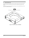
3.4 GMA 240 Installation
NOTE
Avoid installing the unit near heat sources. If this is not possible, ensure
that additional cooling is provided. Allow adequate space for installation
of cables and connectors. The installer will supply and fabricate all of
the cables.
1. Assemble the connector/rack kit according to Tables 4-1, 4-2; and Figures B-1 and B-2. Install
the rack assembly according to the dimensions given in Figures A-1 and A-3. Mounting brackets
are not supplied due to the wide range of mounting configurations available. Suitable mounting
brackets may be fabricated from sheet metal or angle stock. To ensure a sturdy mount, rear
support for the unit should be provided.
2. Slide the unit into the rack until the jackscrew makes contact with the receptacle located in the
back plate.
3. Insert a 3/32” Allen wrench into the jackscrew access hole on the faceplate.
4. Turn the Allen wrench clockwise until the unit is secured in the rack. Continue turning until
tight, but do not over-tighten.
CAUTION
Do not use excessive force when inserting the GMA 240 into the rack.
This may damage the connectors, unit, and/or unit rack. If heavy
resistance is felt during installation, stop, and remove the GMA 240 and
identify the source of resistance.
5. To remove the unit from the rack, turn the Allen wrench counterclockwise until it disengages
from the rack.