


Page 4-6 GMA 240 Installation Manual
Rev. A 190-00917-01
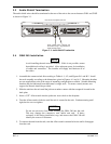
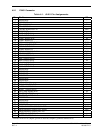
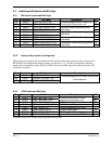
4.5 Audio Inputs/Outputs and Mic Keys
4.5.1 Mic Audio Inputs and Mic Keys
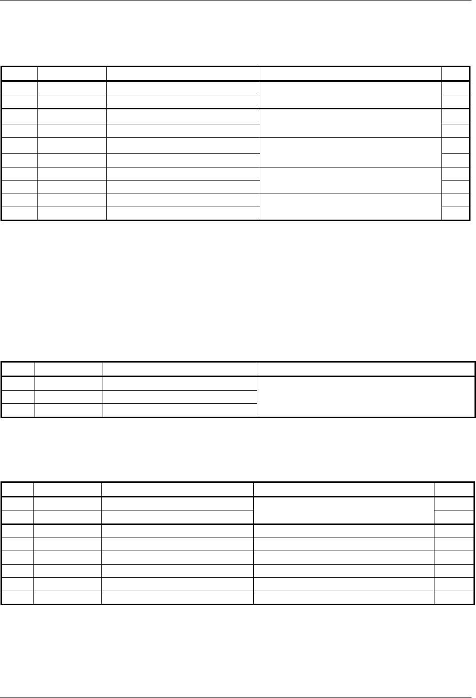
Pin Connector Pin Name Description I/O
34 P2401 PILOT MIC KEY* IN IN
33 P2402 COPILOT MIC KEY* IN
Enables respective MIC audio into
the selected transceiver unit
IN
33 P2401 PILOT MIC AUDIO IN HI IN
35 P2401 PILOT MIC IN LO
Pilot Mic audio input and ground
reference
--
32 P2402 COPILOT MIC AUDIO IN HI IN
34 P2402 COPILOT MIC IN LO
Copilot Mic audio input and ground
reference
--
35 P2402 PASS 1 MIC AUDIO IN HI IN
36 P2402 PASS 1 MIC AUDIO IN LO
Passenger 1 Mic audio and ground
reference
--
37 P2402 PASS 2 MIC AUDIO IN HI IN
38 P2402 PASS 2 MIC AUDIO IN LO
Passenger 2 Mic audio and ground
reference
--
*Denotes Active Low (Ground to activate)
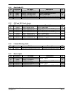
4.5.2 Intercom Key Inputs (if configured)
These inputs only perform the described ICS KEY function if the audio panel has been configured for
KEYED ICS by configuration jumper settings (see Section 2.3.1). For this configuration, intercom
squelch levels should be set fully CCW (live MIC) because the MIC signal must also break the VOX
threshold to be heard.
Pin Connector Pin Name Description
17 P2402 PILOT ICS KEY* IN
36 P2401 COPILOT ICS KEY* IN
37 P2401 PASSENGER ICS KEY* IN
Enables respective mic audio to be heard
in the intercom
*Denotes Active Low (Ground to activate)
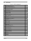
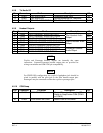
4.5.3 COM Audio and Mic Keys
Pin Connector Pin Name Description I/O
12 P2401 COM 1 MIC KEY* OUT OUT
30 P2401 COM 2 MIC KEY* OUT
Enables transmission on the
respective transceiver unit
OUT
9 P2401 COM 1 AUDIO IN HI COM 1 Audio Input IN
11 P2401 COM 1 MIC AUDIO OUT HI COM 1 Audio Output OUT
10 P2401 COM 1 AUDIO LO Ground Reference for COM 1 --
13 P2401 COM 2 AUDIO IN HI COM 2 Audio Input IN
15 P2401 COM 2 MIC AUDIO OUT HI COM 2 Audio Output OUT
14 P2401 COM 2 AUDIO LO Ground Reference for COM 2 --
* Denotes Active Low (Sinks current to ground when active)