


Electro-Voice® EVA Series User Manual
5.0 EVA Rigging System (cont’)
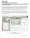
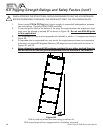
5.3 Assembling and Flying an EVA Array
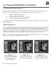
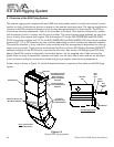
On each end of an EVA module are a pair of upper and lower connection points that accept the supplied
M10 flathead bolts to either (1) attach the side arms of an EVA-SG standard grid or an EVA-EG extended
grid to the top of the upper array module (or bottom of the lower array module as well) or (2) attach the tie
plates supplied with each module so that the modules can be attached to each other. Figure 14 identifies
these parts.
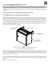
The first step in assembling an array is to attach the two side arms of the grid to the upper array module.
Attach the side arms with the M10 bolts supplied and tighten securely. A single spreader bar is then at-
tached to the side-arm holes shown in EVADA that provide the desired array aiming angle. See section
3.0 Designing an EVA Array, above. When two spreader bars are used they should be attached to the
extreme front and back positions on the side arms, for maximum control over the array’s vertical aiming
angle.
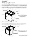
Attach a chain hoist(s) or other lifting device(s) to the assembled grid and the upper EVA module. Then
take the following steps:
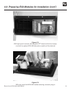
1. Lift the assembly to the point where the second EVA module can just be slipped under the
suspended partial array.
2. Using four M10 flathead screws (provided) attach a tie plate (flat end to the rear) to each
end of the suspended module but do not fully tighten screws.
3. Move the second module into place under the suspended module between the tie plates.
4. Align the holes in the tie plates with the corresponding holes in the lower module and as-
semble to the one above with four M10 flathead screws (provided).
5. Fully tighten all eight M10 screws.
6. Connect the input terminals of the lowest module in parallel with the EVA modules above it.
Repeat the five steps above for attachment of additional EVA modules.
After the last module is attached, even though a tie plate will not be attached to its bottom end panels,
install a pair of M10 screws per end panel where the tie plate would have attached in order to prevent
audible air leaks.
Complete the array by attaching the cosmetic end panels, using the six M5 screws supplied for each
panel. Tighten the screws by hand or use a power drill with a moderate torque setting. Over tightening will
drive the screws through the wood of the end panels!
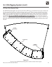
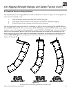
An array will typically be fed from the top down and it is recommended that as each module is added
to the array it should be wired to the one above and the shading selector position set and verified per
EVADA. Attenuation modules (if needed) may also be installed at this time. Note that shading and/or at-
tenuation in the wrong place will seriously detract from the performance of the completed array!
The completed array may now be hoisted into position and secured in the final way intended.
24