


Electro-Voice® EVA Series User Manual 17
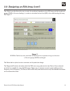
4.0 Preparing EVA Modules for Installation
4.1 Recommended Preflight Procedures
For any installed sound system, certain checks made at the installer’s place of business can prevent ex-
pensive on-site delays. A short-list follows, and sets the stage for proper array performance:
1. Unpack all loudspeakers in the shop.
2. Check for proper model numbers.
3. Check the overall condition of the loudspeakers.
4. Check for continuity at the loudspeaker inputs.
It is a good idea, once on site and the loudspeakers are connected, to check again for continuity at the
power-amplifier end.
4.2 Module Configuration
After the EVADA software has been used to design an appropriate array, the high-frequency (HF) shading
or use of the optional attenuation modules should be noted. In this way, these settings and options can
be configured on the systems as they are rigged together and suspended. (The shading adjustments and
installation of attenuation modules can be completed at the installer’s shop but then care must be taken to
see that the EVA modules are properly identified to avoid misassembly of the array in the field.)
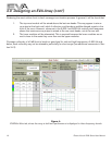
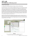
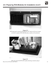
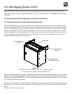
Figure 11 shows an EVA HF shading switch card. This card comes pre-inserted in the “Center = Both @
0 dB” position, indicating no shading of either HF element.
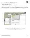
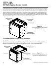
Figure 11b:
EVA input panel, with the
switch card inserted to shade
the lower HF element 3 dB
Figure 11a:
EVA input panel as supplied,
with the high-frequency (HF)
shading switch card in its
central, 0 dB position
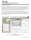
Figure 11c:
EVA input panel, with the
switch card inserted to shade
the upper HF element 3 dB