


Electro-Voice® EVA Series User Manual
4.0 Preparing EVA Modules for Installation (cont’)
To attenuate the top HF element, remove the switch card by drawing it toward you using the central finger
hole. (The switch can also be removed with the end of a flat-blade screwdriver, by placing the blade end
in the switch hole and using the adjacent edge of the input panel as a fulcrum. To facilitate this operation,
there is a small recess in the edge of the input panel adjacent to the hole in switch card.) Reinsert the
switch card one step higher to shade the upper HF element by 3 dB. Reinsert the switch card one step
lower to shade the lower HF element.
Some array designs will also use one or more of the optional EVA-AM attenuation modules. These attach
to the inside of the input-panel assembly using the following steps:
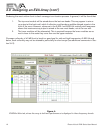
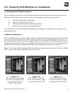
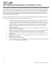
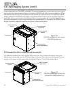
1. Remove the input-panel assembly by removing its eight holding screws with a Phillips #2
screwdriver. The cable assembly that connects the input-panel’s green PC board to the
crossover/equalizer network inside the EVA module is long enough to allow the input-panel
assembly to rest on a flat surface close to the EVA module. If necessary, the crossover/
equalizer cable can be temporarily disconnected. The removed input-panel assembly is
shown in Figure 12.
2. Unplug and discard the 7-pin jumper-wire connector. The attenuation module’s cable con-
nector will replace this connector.
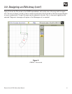
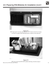
3. With the mounting straps on top, place the attenuation module into the pocket between the
four bosses adjacent to the PC board and secure with the four screws (provided).
4. Plug the attenuation module’s cable into the 7-position header on the PC board as shown
in Figure 13.
5. Apply the supplied label to the input panel around the input connectors as shown on the
EVA-AM Instruction Sheet.
6. Reinstall the input-panel assembly.
7. Connect a short piece of wire (supplied) from the “SELECT” terminal to the terminal marked
-3, -6 or -9 dB, as determined by EVADA.
18