


Electro-Voice® EVA Series User Manual14
3.0 Designing an EVA Array (cont’)
3.4 Other Design Examples
3.41 Dealing with the Relatively High Low-Frequency Variation of Short Arrays
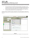
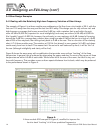
The example of Figure 4 is a three-module array addressing a flat floor from a trim height of 23 ft, with the
first row 10 ft away from the array and the last row 80 ft away. This design opts for very uniform mid- and
high-frequency coverage that hovers around the 0-dB line, with a variation that is well within the opti-
mum ±3 dB at 3,000 Hz (important for vocal intelligibility) and nearly as uniform (±3.5 dB) at 8,000 Hz
(the “sparkle” range). At 500 Hz, however, the uniformity is a non-optimum ±4.5 dB. Instead of hovering
around the 0-dB line, coverage has a distinct bias, rising from about 0 dB at the front to a high of +8 dB
about 25% of the way back, then falling slowly back to 0 dB at the rear. This is a function of the relatively
short, 4.7-ft three-module array. The variation at 100 Hz (not shown) is even greater (± 6 dB), and drops
continuously from front to back. This means that if the sound is well balanced up front, it will be “thin” at
the rear (although intelligibility and clarity will be fine).
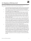
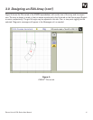
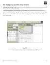
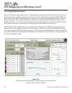
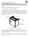
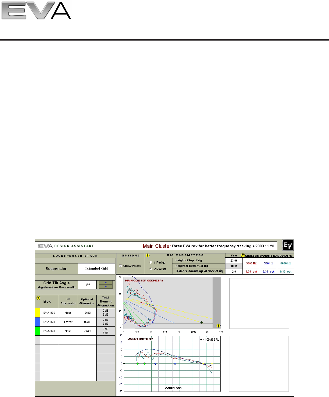
Figure 8 shows the same array with a modification that provides more uniform “tracking” of the three
frequencies. In general, this is achieved by attenuating the upper modules. For most of the venue, all three
frequencies are within ±3 dB of each other. While levels fall at the rear of the room, the falloff is very uni-
form with frequency. This provides a more uniform spectral balance front to back, which may be preferred
to the performance shown in Figure 4.
Figure 8:
A three-module EVA example of Figure 4, modified to improve the
front-to-back “tracking” of all three predicted frequencies