


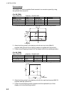
4. INSTALLATION
4-6
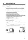
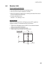
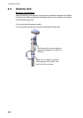
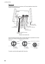
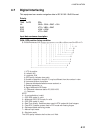
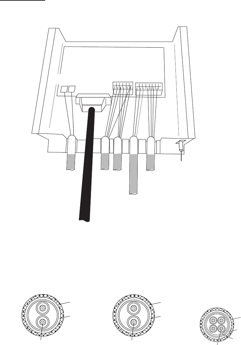
Receiver unit
All cables are gathered to the receiver unit. Connect cables at inside of the
receiver unit as shown below.
DSUB25P-DSUB25P-3M cable
(to Display unit)
DPYC-2.5
(to ship's battery)
RCV Board
08P3227
TTYCS-1Q
(to Navigator
or INS )
DPYC-1.5
(to External alarm)
Printer cable
(to Printer, NX-700B only)
Antenna cable
(to Antenna unit)
TB401
(+)
TB402
(-)
J402*
J403
J401
1 2 3 4 5 6
1 2 3 4 5 6 7 8
Receiver unit, inside view
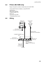
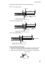
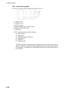
Use the following JIS cable (Japan Industrial Standard) or equivalent to connect
power source, INS and external alarm appropriately.
Conductor
S = 2.5 mm
φ = 2.01 mm
2
DPYC-2.5
Armor
Sheath
φ =
12.5 mm
Conductor
S = 1.5 mm
φ = 1.56 mm
2
DPYC-1.5
Armor
Sheath
φ =
11.7 mm
Conductor
S = 0.75 mm
φ = 1.11 mm
2
TTYCS-1Q (Four core twisted)
Armor
Shield
Sheath
φ = 11.3 mm
For printer, use the cable supplied with the printer.