


Manual Supplement Impulse 6000D/7000DP Users
8 4/08
Change #2
On page 12, prior to Analyzing Pacemakers (7000DP only), add the following section:
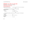
SCOPE OUTPUT
Each time a defibrillator is fired into the Analyzer during an active defibrillator test, a delayed representation of the
defibrillator pulse is sent to the Scope Output jack on the rear panel of the Analyzer. The Scope Output is an
isolated signal and should not present any problems when connected to the input of an oscilloscope.
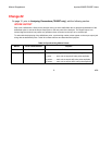
To assist with the displaying of the defibrillator pulse, synchronizing marker pulses appear on the scope output jack
along with the defibrillator pulse. Table 3A list these markers and describes their purpose.
Table 3A. Synchronizing Marker Pulses
Marker Pulse Characteristics Purpose
Defib fire +2 V, 50 ms Indicates when the defibrillator was fired.
Ranging -4 V, 0.4 ms, 1 ms apart Indicates the scaling used to output the pulse image:
1 pulse……….each volt out equals 80 volts pulse amplitude.
2 pulses……...each volt out equals 400 volts pulse amplitude.
3 pulses……...each volt out equals 2000 volts pulse amplitude.