


RGB 109xi and RGB 112xi • Installation
2-6
Controls and Installation, cont’d
RGB 109xi and RGB 112xi • Installation
7
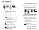
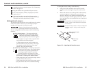
Attach the interface to an audio system. See “Connecting
audio” on page 2-12.
8
Plug the interface into a grounded AC power source.
9
Turn on the computer, monitor, and projector (or other
display device).
10
The image from the computer should appear on the
projector and monitor. If it does not, double check steps
3 through 6 and make adjustments as needed.
Setting internal jumpers
The jumpers inside the interface are set at the factory for optimal
use by most systems. However, you can change a jumper
setting to meet the needs of a particular system.
Changes to internal jumper settings must be
performed by authorized service personnel only.
The user-configurable, internal jumpers control the following
functions:
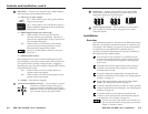
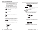
J20: Sync polarity jumper — This jumper adjusts the
output sync polarity. Horizontal (H) and
vertical (V) sync output can either follow
input sync polarity, or be forced to negative.
• If the jumper is on pins 1 and 2, output H and V
sync polarities are forced to negative.
• If the jumper is on pins 2 and 3, output sync
polarities follow input sync polarity: The output
sync signals’ polarity is the same as the input
polarity. This is the default setting.
J40: Vertical sync width jumper — This jumper adjusts the
vertical sync pulse width. Some digital display
devices have very specific requirements for
incoming sync pulse width. If no picture
appears, the picture cuts in and out, or the
picture is scrambled, try adjusting the vertical sync
pulse width or switching from ADSP to DDSP.
• If the jumper is on pins 1 and 2, the output vertical
sync pulse will be short (narrow).
• If the jumper is on pins 2 and 3, the output vertical
sync pulse will be wide. This is the default setting.
Negative
Follow
1
Wide
Short
1
2-7
To change the jumper settings, do the following:
1. If the power cord is attached, remove power from the
interface by disconnecting the AC power cord from the
unit.
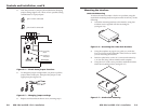
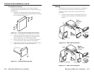
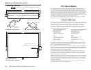
2. Remove the interface cover (the top half of the enclosure),
as shown in figure 2-3. Remove the screws from the
enclosure, slide the cover slightly towards the back of the
enclosure, enough to clear the gain/peak switch, lift the
cover, and place the cover upside down next to the base of
the enclosure.
CAUTION
Do not pull on the cable that attaches the cover to
the base. Doing so could disconnect the cable from
its connectors.
CAUTION
Do not touch any switches or electronic components
inside the interface. Doing so could damage the
interface.
Remove (5)
screws.
Slide cover back slightly,
lift straight up.
Figure 2-3 — Opening the interface cover