


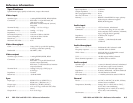

2-12
RGB 109xi and RGB 112xi • Installation
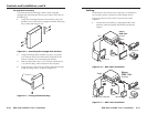
Controls and Installation, cont’d
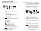
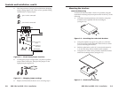
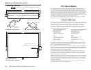
2. Connect the interface cable marked “Video input” to
the computer’s video output (where the monitor was
originally connected).
3. Connect the audio cable connector on the interface cable
to the computer’s audio line output (where the powered
speakers were originally connected).
4. Use BNC cables to attach the interface to a projector or
other display device.
RGsB – If coax cables are connected and terminated (75 ohms)
to the red, green, and blue channels only, and the
SOG switch is set to On (see page 2-4), the output
is sync on green.
RGBS – If the S (composite sync) cable is connected, the output
is composite sync.
RGBHV – If both the H & V cables are connected, the sync
output is separate horizontal and vertical.
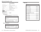
Connecting audio
Before connecting audio, determine whether your audio system
is unbalanced or balanced. Then, follow the instructions on
page 2-12 or 2-13, to connect unbalanced or balanced audio.
CAUTION
Wiring the audio incorrectly may damage the audio
output circuits.
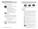
Unbalanced audio
To attach the interface to an unbalanced audio system, do the
following:
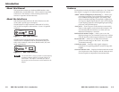
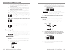
1. Attach the audio cable to an unbalanced speaker input
connector (tip and sleeve).
Tip Sleeve
RGBHV
R
H
G
V
B
S
RGBS
R
H
G
V
B
S
RGsB
R
H
G
V
B
S
RGB 109xi and RGB 112xi • Installation
2-13
2. Attach the audio cable to the captive screw connector
(Extron part number 10-319-10) as shown below. Fasten
down the captive screws inside the audio cable connector.
Unbalanced Output
Tip
See Warning
Sleeve (s)
Tip
See Warning
CAUTION
Connect the sleeve(s) to ground (GND).
Connecting the sleeve(s) to a negative (-) terminal
will damage audio output circuits.
3. Slide the audio cable connector into the audio output
connector on the interface.
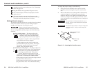
Balanced audio
To attach the interface to a balanced audio system, do the
following:
1. Attach the audio cable to a balanced speaker input
connector (tip, ring, and sleeve).
Tip (+) Sleeve
Tip (+)
Ring (-)
Sleeve
2. Attach the audio cable to the captive screw connector
(Extron part number 10-319-10) as shown below. Fasten
the captive screws inside the audio cable connector.
Balanced Output
Tip
Ring
Sleeve (s)
Tip
Ring
3. Slide the audio cable connector into the audio output
connector on the interface.