


RGB 109xi and RGB 112xi • Installation
Controls and Installation, cont’d
2-8
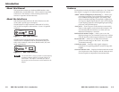
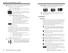
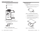
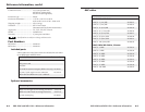
3. Note the positions of jumpers J20 and J40 before changing
jumper settings (figure 2-4). There are two possible setting
combinations for 3-pin jumpers:
1 and 2
pins 1 and 2 connected
2 and 3
pins 2 and 3 connected
J19
1
J40
1
J20
1
Front
Rear
Power Supply
J20: Sync
polarity
jumper
J40: Vertical
sync
width
jumper
Figure 2-4 — Circuit board jumper locations
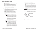
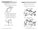
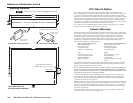
4. To change the jumper configuration, use pliers to pull the
jumper shunt off the pins, then place the jumper on the
appropriate pins (figure 2-5).
Figure 2-5 — Changing jumper settings
5. Replace and fasten the enclosure cover, reversing step 2.
RGB 109xi and RGB 112xi • Installation
2-9
Mounting the interface
Under-desk Mounting
To mount the interface under a desk or in a podium using the
under-desk mounting kit (Extron part number 70-077-01), do the
following:
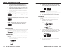
1. Attach the mounting brackets to the interface using four
machine screws supplied with the mounting kit
(see figure 2-6).
Figure 2-6 — Attaching the under desk brackets
2. Using the template on page A-6 to guide you, mark the
four screw holes on the underside of the surface to which
you are mounting the interface.
3. Drill four pilot holes, each 3/32" (2.4 mm) in diameter by
1/4" (6.4 mm) deep, where marked on the template.
4. Using the four wood screws provided, attach the brackets
under the mounting surface (see figure 2-7).
Figure 2-7 — Under-desk mounting