


RGB 109xi and RGB 112xi • Installation
Controls and Installation, cont’d
2-2
Front and Rear Panels
Front panel features
RGB 109xi
BUFFERED LOCAL
MONITOR OUTPUT
H. SHIFT
INPUT
VGA INTERFACE WITH ADSP
ID PIN 4
ID PIN 11
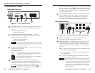
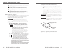
Figure 2-1 — Front panel features
1
Video Input cable — Attaches the interface to the computer or
workstation. The type of connecter depends on the interface
model:
RGB 109xi: 15-pin HD male
RGB 112xi: 13W3 male
2
Buffered Local Monitor Output Connector — Attaches to
the local monitor’s video signal cable. The type of connector
depends on the interface model:
RGB 109xi: 15-pin HD female
RGB 112xi: 13W3 female
If you are not using a local monitor with the RGB 112xi,
you must attach an MFTA (multi-frequency termination
adapter) to simulate a monitor.
3
ID Pin switches (RGB 109xi only) — Allows the user to set the
correct ID bit termination:
ID PIN 4 & ID PIN 11
On — Set both pins to On (up) if you are using the
RGB 109xi interface with a laptop computer that is
not attached to a local monitor.
Off —Set both pins to Off (down) if you are attaching
a local monitor to the interface.
4
Horizontal Shift control — Controls the screen image
horizontal centering. To adjust the horizontal shift, turn the
knob in either direction and observe the left/right movement of
the image on the screen. Stop when the image is centered.
If the DDSP
™
DIP switch on the rear panel (
3
) is set
to On, the horizontal shift control is disabled.
1
2
3
4
5
ID PIN 4
ID PIN 11
RGB 109xi and RGB 112xi • Installation
2-3
While the horizontal shift control is active, "H-SHIFT" appears in
the scan rate indicator LCD (
5
) and for a further three seconds
after the control is no longer active. When the control reaches its
maximum or minimum point, "MAX" or "MIN" appears in the
scan rate indicator LCD.
5
Scan rate indicator LCD — Shows the scan rate for the selected
input, in kilohertz (kHz), on the top line. The vertical scan
frequency, in Hz, appears on the bottom line. In addition, if
the horizontal shift control is activated, or the minimum or
maximum limits are reached, the LCD displays the status.
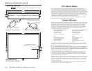
Rear panel features
SOG
DDSP
SERR
SPARE
100-240 0.5A MAX.
50/60 Hz
IBM
SGI
SUN
SOG
OUTPUT
R
H
G
V
B
S
UNITY
50%
100%
GAIN/
PEAK
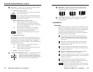
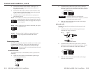
Figure 2-2 — Rear panel features (RGB 112xi shown)
1
IEC AC power connector — Use this standard AC power
connector with the supplied IEC power cable.
2
Gain/peak switch — Compensates for cable capacitance if the
signal cable between the interface and the display device is
longer than approximately 125 feet (38m). Turn the switch to
the position that provides the best image on the output display
device.
100% — Increases the output signal level and adds 100% of the
maximum peaking to the signal.
Unity — The output level is the same as that of the input, with
no added peaking.
50% — Increases the output signal level and adds 50% of the
maximum peaking to the signal.
If the signal cable between the interface and the display
device is shorter than approximately 125 feet (38m), and
the Gain/Peak switch is set to a setting other than Unity,
the image may be overcompensated. If the edges of the
image seem to exceed their boundaries, or if thin lines
and sharp edges look thick and fuzzy, try changing the
Gain/Peak settings.
1
2
3
4
5
6