


Installation, cont’d
MGP 464 • Installation
2-6
PRELIMINARY
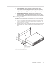
b
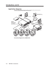
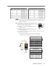
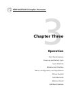
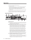
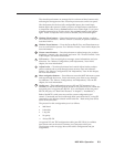
Virtual inputs (inputs 5 through 19) — Connect standard definition
component video, S-video, and/or composite video sources to these BNC
connectors. The 15 connectors for the virtual inputs are arranged in columns
of three BNCs.
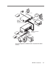
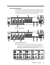
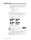
In each column, you can connect inputs as follows (see the illustration below):
Up to three composite video inputs (can be plugged into any •
connector[s] in the column)
One S-video input and, optionally, one composite video input•
The S-video must always be connected to the top two BNC
connectors. The Y connector must be on top, the C connector in the
middle). If desired, a composite video source can be connected to the
bottom BNC connector.
One interlaced component video source (must be connected to all •
three BNC connectors in the column).
VID
Y
VID
B-Y
C
VID
R-Y
5
6
7
VID
Y
VID
B-Y
C
VID
R-Y
5
6
7
S-video
and
Composite
Component
VID
Y
VID
B-Y
C
VID
R-Y
5
6
7
Composite
Virtual input connector configuration examples
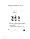
You can configure these virtual inputs for the desired signal types using
the Windows-based control software (see the control software help le), SIS
commands (see chapter 4, “Software Conguration and Control”), or the Web
pages (see chapter 5, “HTML Conguration and Control”). They cannot be
configured via the front panel.
N
When you configure a virtual input as S-video (using two input connectors)
or component video (using three input connectors), pressing any one of its
equivalent buttons selects the input. For example, if you plug an S-video source
into input connectors 8 and 9, pressing either the 8 or the 9 input button selects
that input.
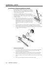
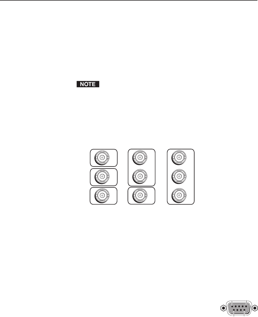
c
RS-232/422 connector — Plug a computer or other RS-232 or
RS-422 host device into this connector. Wire the connector
as shown on the next page. See chapter 4, “Software
Conguration and Control,” for more information on
controlling the MGP 464 remotely.
5
1
96