


DVI 201 Tx/Rx • Installation and Operation
Installation and Operation, cont’d
2-32
DVI 201 Tx/Rx • Installation and Operation
2-33
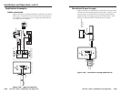
Application Examples
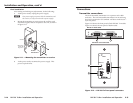
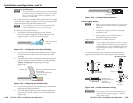
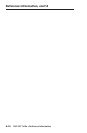
Audio conversion
Figure 2-28 shows a standard installation with DVI video and an
audio input. The DVI 201 A D Tx converts the video input into
two proprietary TP outputs. The Tx outputs the audio directly
on a captive screw connector.
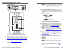
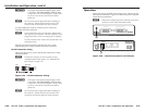
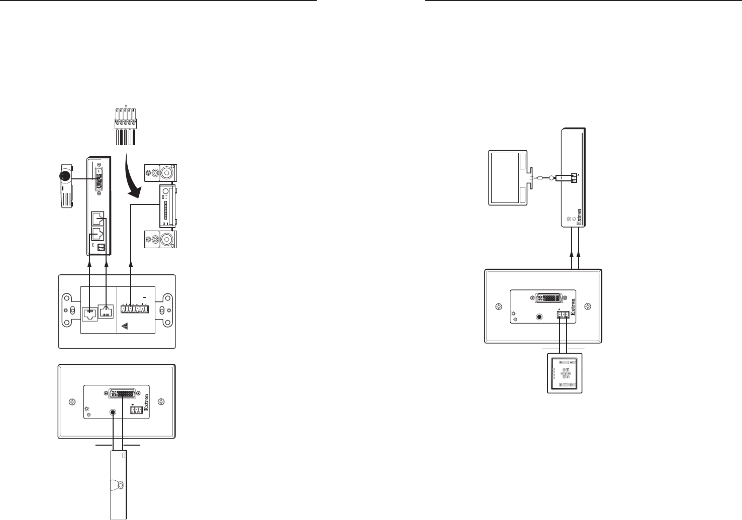
Modulated IR pass through
Figure 2-29 shows an installation in which the Tx/Rx pair sends
a modulated infrared (IR) signal across the link. On the TX side,
control system is connected to the Tx pin (the modulated IR
signal) and the Gnd (signal ground) on the transmitter. An IR
emitter is connected to the Tx and Gnd receiver output.
Figure 2-28 — Typical installation
POWER
12V
0.4A MAX
DVI 201 RX
1 2
DVI OUTPUT
POWER
12V
0.4A MAX
L
AUDIO
OUTPUT
R
DO NOT
CONNECT
TO LAN
1
2
DVI 201
A D Tx
O
U
T
P
U
T
S
INPUT
Rx
Tx
RS-232
PASS THRU
DVI
AUDIO L+R
DVI-D In
Source
Audio
TP 1
TP 2
Balanced Audio Out
Balanced Audio
Wiring
Audio System
DVI 201 A D Tx Front DVI 201 A D Tx Rear
DVI 201 Rx
Projector
R+
R-
L+
L-
Figure 2-29 — Installation routing modulated IR
TP 1
TP 2
INPUT
Rx
Tx
RS-232
PASS THRU
DVI
AUDIO L+R
DVI 200 RX SERIES
RS-232
PASS THRU
Tx Rx
IR Emitter
Ground
Control
System
Modulated IR
DVI 201 Rx
DVI 201 A D Tx
Flat Panel Display
w/ IR Control