


DVI 201 Tx/Rx • Installation and Operation
Installation and Operation, cont’d
2-16
DVI 201 Tx/Rx • Installation and Operation
2-17
POWER
12V
0.4A MAX
DVI 201 Tx
RS-232
PASS THRU
Tx Rx
DDC ROUTE
1 2
REMOTE
SPARE LOCAL
POWER
12V
0.4A MAX
L
AUDIO
OUTPUT
R
DO NOT
CONNECT
TO LAN
1
2
DVI 201
A D Tx
O
U
T
P
U
T
S
5 6 4
7
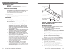
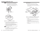
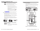
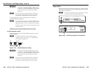
DVI 201 Tx Rear Panel
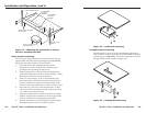
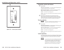
DVI 201 A D Tx Rear Panel
6
5
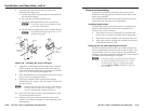
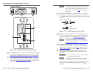
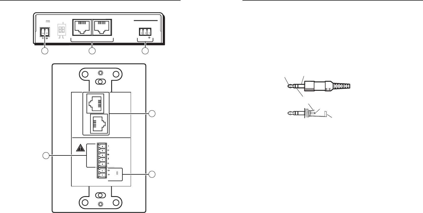
Figure 2-13 — DVI 201 Tx rear panel connectors
a
DVI input connector — Connect a DVI cable between this port
and the DVI output port of the digital video source. See "DVI
connector pin assignments," on page 2-22, for pin assignments.
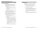
b
Local output (DVI 201 Tx ([non-Decora] only) — If desired,
connect a DVI monitor for local monitoring of the input digital
image. See "DVI connector pin assignments," on page 2-22, for
pin assignments.
N
In a system where the local output is not used, ensure
that you power up the end display first before the video
source. Route the DDC to the remote end (see the
DDC Route DIP switch [item
b
, in "Operation", on
page 2-29]).
c
Audio input (DVI 201 A D Tx [Decora] only) — Connect an
unbalanced stereo audio source to this 3.5 mm mini stereo jack
for unbalanced audio input. Figure 2-14 shows how to wire the
audio plug.
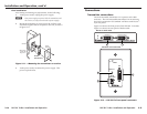
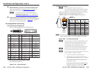
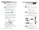
Tip (L+) Sleeve (Gnd)
Tip (L+)
Ring (R+)
Sleeve (Gnd)
Figure 2-14 — Audio input connector wiring
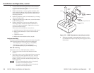
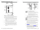
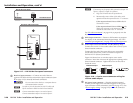
d
RS-232 connector — Connect a serial communications port to
this 3.5 mm, 3-pole captive screw connector for bidirectional
RS-232 communication. See "RS-232 connector wiring," on
page 2-26, to wire the connector.
N
The RS-232 connector can also transmit one-way
modulated infrared (IR) signals. See "Modulated IR
pass through" on page 2-33.
e
DC power input connector — Plug the included external
12 VDC power supply into either this connector or the power
input connector on the receiver (item
k
on page 2-20). See
"Power supply wiring," on page 2-25, to wire the connector.
f
Transmitter output connector — Connect one end of two
separate TP cables to these RJ-45 female connectors on the
transmitter.
C
Do not connect these devices to a computer data or
telecommunications network.
N
In order to fit in the junction box, the TP cables and
RJ-45 connectors should not have a boot installed.
Connect the free ends of the same TP cables from the transmitter
to the receiver’s Input RJ-45 female connectors (item
h
on
page 2-21).