


2. Check power on the lower channel. Adjust C124 in the
direction that increases power output to a level half way
between the initial lower and upper channel levels.
3. Recheck the upper channel power. If the upper channel
power is reduced, reset to the previous level by adjust-
ing C126.
4. Repeat this procedure until the power out on both
channels is equal (±.1W).
• For frequency spreads ≤ 10 MHz - power out ≥
power minimum
• For frequency spreads > 10 MHz - power out ≥
power minimum - 1dB
Supply current levels should not exceed 1100 mZ
(10V) or 800 mA (7.5V) with wide band tuning.
TX Modulation Set
With the transmitter keyed, apply a 1 kHz tone at 100 mV
RMS to the MIC input. Adjust R230, located on the Synthe-
sizer Board, until the following peak deviation is measured on
the output modulation analyzer:
With Channel Guard - 4.5 kHz (±100 Hz)
Without Channel Guard - 3.75 kHz (±100 Hz)
RECEIVE ALIGNMENT
Change to a receiver test setup, with a frequency modu-
lated RF signal generator connected to the antenna jack J3. Set
the input RF signal to the highest programmed receive fre-
quency and modulate it with a 1 kHz tone at 5 kHz peak
deviation. Use a signal level high enough to measure the level
of the 455 kHz 2nd IF signal at test point J501 with an RF AC
voltmeter. Proceed with the following alignment procedure.
IF Alignment
Adjust the RF signal level for linear operation at J501.
Tune L502 and L504 for a maximum IF signal level at J501.
An alternate method for making the IF alignment is as
follows. Tune L502 and L504 for minimum audio distortion
while monitoring the speaker output. Use either 5 kHz or 3 kHz
of deviation.
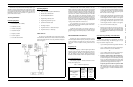
Second LO Frequency Set
Remove all modulation from the input signal and increase
the level to 0 dBm. Monitor the frequency at J501 and adjust
L505 in the crystal oscillator circuit for 455 kHz ±100 Hz.
Quadrature Detector Set
Modulate the RF input signal with a 1 kHz tone at 3 kHz
peak deviation. Load the speaker output at the accessory con-
nector with 8 ohms to ground. Monitor the speaker output from
the accessory connector while tuning L506 in the quardrature
detector for a maximum audio level.
L.O. Notch Tuning
When it necessary to limit the L.O. leakage out the antenna
port to a level less than -60 dBm, (Canadian D.O.C. RSS 119,
121 require -53 dBm for portables with batteries, otherwise -57
dBm) the L.O. notch filter may be tuned to the receiver L.O.
frequency to meet this requirement. Observe the L.O. signal
level at the antenna port on a spectrum analyzer capable of
reading -70 dBm. Select the channel with the lower operating
receive frequency and tune the notch filter adjustable capacitor
(C136) for a minimum level. Check the level on the higher
receive frequency. If greater than -60 dBm, turn the capacitor
(C136) in the direction that lowers the level to the point that
-60 dBm is reached and stop. Recheck the lower receive
frequency.
TROUBLESHOOTING
This section provides a guide to troubleshooting the MPI-
II VHF radio. The following procedures will assist in de-
terming if the problem is in the RF circuits (Transmitter,
Receiver or Synthesizer) or the Control circuits. The test set-up
should be the same as that used in the Alignment section of this
manual.
Documentation To Help In Troubleshooting
• RX and TX block diagrams with RF gains and
levels
• Synthesizer block diagram
• Control Circuits block diagram
• Audio Processing block diagram
• Interconnection diagram
• Outline diagrams
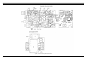
• Schematic diagrams
• Parts lists
• IC data
TRANSMITTER
Transmit Power Output Problem, Inoperative
or Low
1. Power sources and regulated power supplies should
be checked before troubleshooting any transmitter
problem. The radio’s power source, whether a battery
or bench power supply, is especially important in
troubleshooting a personal radio. Current consump-
tion offers an excellent clue in the case of a dead or
weak transmitter. See Table 3 in the Battery Informa-
tion section on typical current consumption for dif-
ferent operating conditions. Check supplies as
follows:
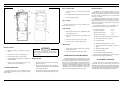
a. Check for battery B+ voltage at J12-01, or inside
fuse F1/switch S1. It should be present at the
driver Q104 and final amplifier Q105, and meas-
ure 7.5 Vdc for 2-watt radio, 10 Vdc for 4-watt
radio.
b. Check for presence of B+ SW on buffer ampli-
fier Q106 and predriver Q103. It should switch
ON under control of the PTT switch through B+
switch Q805.
c. Check 5.4 V from 5.4 V regulator, which is
required for and available on the Synthesizer
board.
2. An early step in troubleshooting for the cause of low
RF output power is to check that the programming is
correct.
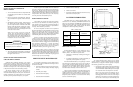
SYMPTOM POSSIBLE CAUSES
Completely inopera-
tive (no audio)
• Dead Battery Pack
• Fuse blown
• Control circuit problem
At power-up radio
beeps continuously
• Weak battery pack
• Unit is not programmed
• Synthesizer is not locked
Receiver inoperative
or weak
• Squelch level set too high
• Channel Guard enabled
• Defective antenna
• T/R Board problem
Transmitter inopea-
tive or low range
• Power levels set too low
• Weak battery
• Defective antenna
• T/R Board problem
Tx and Rx inopera-
tive on one or both
channels
• Programming incorrect
• Synthesizer problem:
VCO, prescaler, or
lock detect
Tabel 2 - General Troubleshooting Guide
NOTE
Throughout the service procedures, the following
information should be observed:
• The bench power should be set for 7.5 Vdc
(±0.1 Vdc) for a 2 watt radio, or 10.0 Vdc (±0.1
Vdc) for a 4 watt radio. If a battery pack is
used, it should be fully charged. Typical battery
pack voltage should be within ±20% of set
voltage over its full discharge cycle.
• Logic Levels should be:
Logic 1 = high ≤ 4.5 Vdc
Logic 0 = low ≥ 0.5 Vdc
• Modules are not field repairable. Schematics
and Outline drawings for the modules are pre-
sented for troubleshooting reference only.
• The personality information stored in the radio
should be backed up on the PC computer before
any service procedure.
S
E
R
V
I
C
E
S
E
C
T
I
O
N
LBI-38557 LBI-38557
5