


FRONT COVER
1. Remove the battery as described in the previous
section.
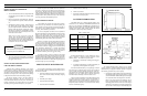
2. Remove the two screws at (A) (See Figure 2).
3. Carefully lift the front cover from the radio.
4. Unplug the cable between the front cover MIC Board
and the T/R Board.
5. To gain access to the microprocessor, remove the
three screws at (B) and lift up the cover.
SYNTHESIZER BOARD
The Synthesizer Board may be separated from the
Transmit/Receive Board by prying the connectors straight
out from the pins.
REAR COVER
1. Remove the screw at (C) using a No. 7 TORX screw-
driver (See Figure 2).
2. Remove the four M2 pan head screws, 3 at (B) and 1
at (H), on the component side of the T/R Board using
a No. 7 TORX screwdriver.
3. The RF Board with the top cover and the side panel
attached may now be removed from the rear cover.
BNC CONNECTOR
1. Remove the No. 3-48 x .125 setscrew (D) using a 0.050
hex tool.
2. Unsolder the BNC center pin from the antenna contact.
3. Remove the BNC connector.
UDC COVER
Remove the M2.5-0.45 screw using a flat blade screw-
driver or the edge of a coin.
TOP COVER
1. Pull off the two knobs from the ON/OFF/VOLUME
and the Squelch control.
2. Remove the Spanner nuts (E) using a Spanner Tool
ST2311.
3. Remove the 1/4-40 (F) nut using a 5/16 wrench.
4. Remove the top cover from the T/R assembly.
SIDE PANEL
1. Remove the two Audio Jack Spanner nuts (G) using a
Spanner Tool ST2312.
2. Remove the side panel from the T/R Assembly.
PERSONALITY PROGRAMMING
The MPI-II Personal Radio is equipped with a 256 x 8 bit
serial personality EEPROM. All cutomer information such as
the customer frequencies, customer tones and customer op-
tions are stored in the EEPROM. The EEPROM contains all
information to tailor the operation of the radio to the user’s
requirements. The EEPROM is programmed by using an IBM
compatible personal computer with MSDOS, Interface Box
19D438367G1, RS-232 Cable 19B235027P1, Programming
Cable TQ-3352 and Programming Software TQ-3351.
PROGRAMMING
The MPI-II radio is programmed through a test cable
connected to the accessory connector located on the side of the
radio. Power is applied to the battery terminals located on the
rear radio assembly. B+ should be 7.5V for a 2 watt radio and
10.0V for a 4 watt radio.
Programming information must be written to the person-
ality PROM before alignment or performance tests. This is
always done through the accessory connector and cable. This
cable may be attached to the radio and left connected during
the entire test procedure.
The assigned frequencies to be used should be pro-
grammed into the personality of each 2-channel radio:
First Transmit frequency Tx F1
First Receive frequency Rx F1
Second Transmit frequency Tx F2
Second Receive frequency Rx F2
The radio’s chosen options must alos be programmed in:
• Channel Guard (with C.G. frequency)
• No Channel Guard
• Digital Channel Guard (with D.C.G. code)
• Type 99 Tone (with Tone A Frequency, Tone B Fre-
quency)
• Talk-around (enable, disable)
• STE (enable, disable)
• Channel Busy Inhibit (enable, disable)
Detailed programming instructions should be followed as
found in the TQ-3351 Programming Manual.
ALIGNMENT AND TEST
Initially, the Receiver of the MPI-II Personal Radio is
aligned and ready for use before leaving the factory. The
Transmitter is tuned at the high end of the band, with retuning
recommended for optimum operation when another frequency
is selected. This section provides procedures for aligning and
testing the MPI-II VHF (136-174 MHz) Personal Radio.
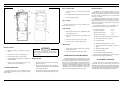
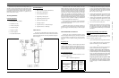
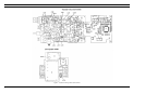
Figure 2 - Disassembly
When separating the Synthesizer and Transmit/Re-
ceive boards, care should be taken not to bend the
connector pins.
CAUTION
LBI-38557 LBI-38557
2