


Several tests are presented which will help isolate a pos-
sible RF or control circuit problem. The control circuits, which
are located on the T/R Board, contain no adjustments and there
is no alignment required for the control circuits. See the Trou-
bleshooting section for test information if a problem is sus-
pected in the control circuits.
TEST EQUIPMENT
General Equipment
1. RF Generator (136-174 MHz)
2. Wattmeter (5 watts)
3. Ammeter (2 amperes)
4. Distortion Analyzer
5. Frequency Counter
6. Test Box TQ-0613
7. Test Cable 19C851752P8
Special Equipment
1. IBM Compatible Computer with MS-DOS
2. Interface Box 19D438367G1
3. RS-232 Cable19B235027P1
4. Programming Cable TQ-3352
5. Programming Software TQ-3351
6. Synthesizer Extender Cable
7. Discharge Analyzer
8. Alignment Tool, 0.1" slotted (metal) tips
9. Alignment Tool, 0.1" slotted tips.
TEST SET UP
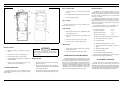
To gain access to adjustable circuit components for align-
ment of the radio, the front cover must be removed as described
in the Disassembly Section. A test setup should be arranged as
shown in Figure 3.
Connect the leads of the dummy battery to the two
battery terminals accessble in the open radio. The external
power leads from the dummy battery will be connected later.
Connect the TQ-0613 Test Box to the radio using the UDC
connector. An audio oscillator can be used as an audio input
to the Text Box. Connect a distortion analyzer to the audio
output of the Test Box. For transmitter operation, an RF
power meter/modulation analyzer should be connected to the
antenna connector J3 in place of the antenna. A frequency
meter can be coupled to the output using a coaxial directional
coupler. For receiver operation a frequency modulated RF
signal generator should be connected to J3.
For programming, the TQ-3301 serial programmer
would alternatively be connected through the UDC connec-
tor on the side of the radio.
Set the DC power supply to 7.5 volts(±0.1 volts) for a 2
watt radio, or 10 volts (±0.1 volts) for a 4 watt radio. Connect
the power supply to the dummy battery as shown in Figure
3.
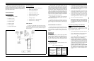
TRANSMITTER ALIGNMENT
With the test setup for transmitter operation in place,
select the highest transmit frequency and key the radio ON
to find an indication of output power on the power meter.
See Figure 4 for the location of tuning controls and test
points.
Frequency Set
Measure the frequency of the RF output signal with the
frequency meter. It should be within ±100 Hz of the pro-
grammed frequency. Should a small adjustment be neces-
sary, this change can be made by tuning the Reference
Oscillator (TCXO) module U203 on the Synthesizer Board.
Set Transmitter Power
The following sequence should be followed for maxi-
mizing rated output power:
1. With the highest transmitter frequency selected, tune
C118, C124, C126 for maximum output power meas-
ured with the Power Meter. The power out should be
greater than 4.5 watts with 10V supply and greater
than 2.5 watts with 7.5V supply.
2. Adjust C126 for minimum DC current drain from the
power supply until the power output is 4.2-4.3 watts
for 10V supplies and 2.2-2.3 watts for 7.5V supplies.
3. Adjust C118 for minimum DC current drain from the
power supply until the power output is 4.0-4.1 watts
for 10V supplies and 2.0-2.1 watts for 7.5V supplies.
4. Tune C124 for maximum outut power.
5.
Return C126 for 1050 mA (±10 mA) for 10V sup-
plies and 750 mA (±10 mA) for 7.5V supplies. Check
the output power. The output power should be equal
to or greater than the minimum power as listed in the
table above.
Customer Programming And Wide Band
Tuning
This section describes the programming and adjust-
ments for wide band tuning. The following steps (1-4) are
for preset customer frequencies with:
– Up to 10 MHz spread with no degradation from Pref
– Up to 17 MHz spread with less than 1 dB of degra-
dation from Pref in the 136-153 MHz band
or
– Up to 24 MHz spread with less than 1 dB of degra-
dation from Pref in the 150-174 MHz band
1. Frequency spreads greater than 10 MHz only -
Program the radio on a channel mid way between the
two desired frequencies. Tune the radio by following
Steps 1-5 in the Set Transmitter Power section. Then
reprogram the customer frequencies and measure the
power out on the upper channel. Go to Step 2.
Frequency spreads less than or equal to 10 MHz
only -Program the radio on the customer frequen-
cies. Tune the radio on the higher frequency channel
by following Steps 1-5 in the Set Transmitter Power
section.
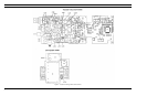
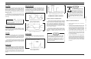
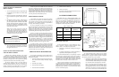
Figure 3 - Test Setup
2 WATT 4 WATT
RADIOS RADIOS
Battery or Supply 7.5 10
Voltage VOLTS VOLTS
Minimum Output 1.9 3.8
Power WATTS WATTS
Table 1 - Minimum Output Power
S
E
R
V
I
C
E
S
E
C
T
I
O
N
LBI-38557 LBI-38557
3