


ELECTRO-VOICE
®
7
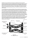
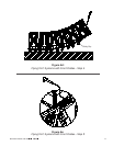
Specifically, this means that when the enclosures are suspended, the back of the bottom
enclosure will rotate down until the pin is stopped at the end of the slot in the swing arm. This one
pin will not prevent the back corners of the enclosures from coming together. When landed, the
enclosures will compress together until their back corners touch. The enclosures can be locked
apart by inserting a second quick-release pin in the rear rigging holes directly above the first pin
at the end of the swing arm as shown in Figure 5. With a second pin, the swing arm becomes
immobile and the array becomes rigid so that when it is landed, the enclosures are locked at the
selected angles.
Two quick-release pins on lanyards are attached to the rear rigging frame for pinning the swing
arm. An XLC system can often be flown using only a single pin - the one that passes through the
slot in the swing arm. The choice of whether to add the second pin is left to the user. This decision
is often based on personal preferences regarding the technique of transferring the enclosures
from the array to dollies for transport in touring applications. In some situations, however, the
second pin is required. Two pins must always be used whenever a pull back is necessary to tilt
the entire array downward more than gravity will allow. If a second pin is not used, the shape of
the array will change as the pull back is applied. Another example where a second pin is required
is when an array with a large vertical arc is created. Gravity may not allow all the enclosures to be
angled apart as much as necessary. In this case, the second pin is necessary to hold the
enclosures apart to achieve the desired array shape. If the user decides not to use the second pin
to hold enclosures apart at the rear, the pin should be installed in the swing-arm transport hole to
prevent it from dangling and catching on something or getting in the way. Using this hole, the
swing arm may be pivoted down into the rigging slot on the frame and pinned into its fully
retracted position for transport.
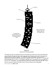
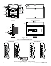
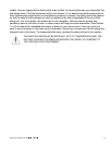
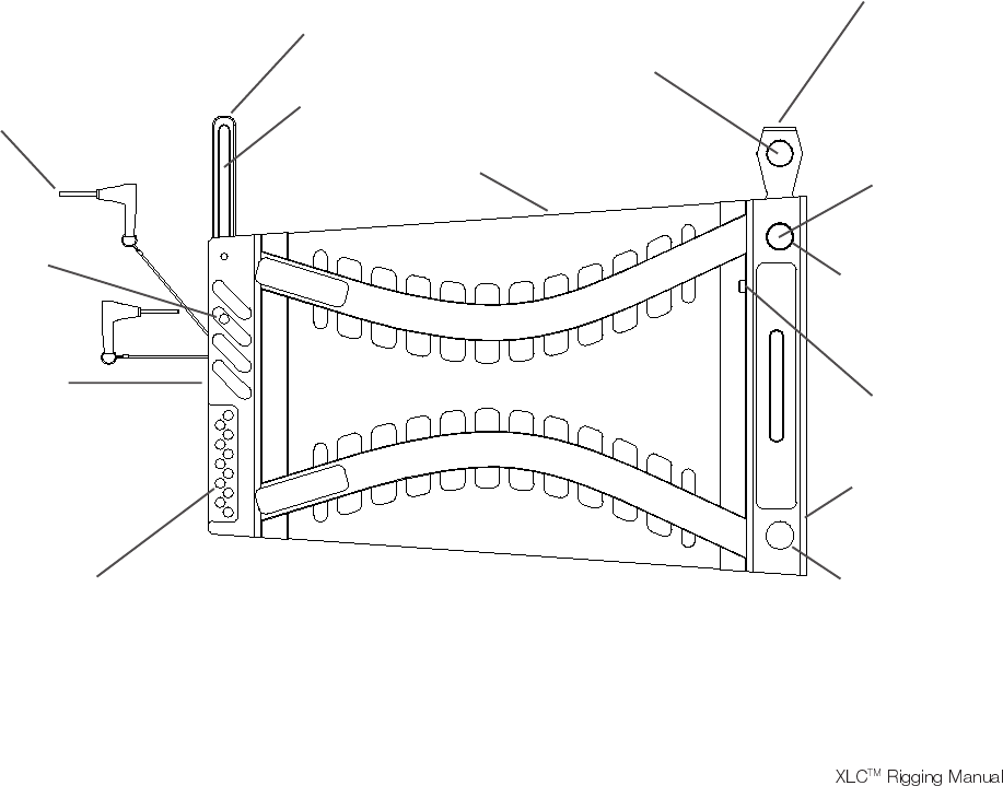
Quick-Release Pins to
Lock Swing Arm in Rear
Rigging Slot
Bottom Spring-
Loaded Locking
Button
Rear Rigging Slot
Swing-Arm Slot
Rear Swing Arm
XLC Enclosure
Top Spring-Loaded
Locking Button
Front Button Bar
Hole in Rigging
Tube for Locking
Button
Front Rigging Tube
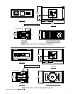
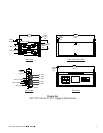
Figure 3a:
XLC Rigging Hardware
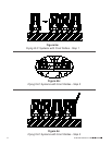
Holes in Rigging Slot to
Pin the Swing Arm from
the Box Below
Hole in Rigging
Tube for Locking
Button
Button Bar Knob
Swing-Arm
Transport Hole