


ELECTRO-VOICE
®
5
1. XLC Rigging System
1.1 Overview of the XLC Flying System
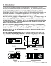
The XLC loudspeaker systems have been designed to construct acoustic line arrays. Acoustic line
arrays typically consist of independent columns of loudspeaker systems. This simplifies the
rigging system.
The XLC loudspeaker enclosures utilize a hinged rigging system that makes constructing arrays
easy, predictable and repeatable. This front-hinging rigging concept allows arrays to be
constructed with the least possible spacing between enclosures. The front and back rigging
hardware for linking two enclosures together are captured as an integral part of the side rigging
frames.
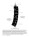
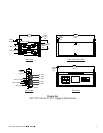
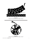
A basic array is shown in Figure 2 that illustrates the integral components that make up a typical
XLC flying system. The XLC enclosures are vertically trapezoidal - taller at the front than at the
back. The enclosures are hinged at the front corners using rigging hardware specially designed
for the XLC system. The enclosures are linked at the rear using rigging arms that have multiple
attachment positions. The different positions adjust how close the back corners of the enclosures
are pulled together; hence, adjusting the vertical angle of the bottom enclosure.
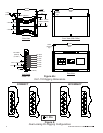
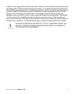
1.2 XLC Enclosure Rigging Hardware Details
On each side of the enclosure is an XLC rigging frame assembly. All the rigging hardware needed
to fly a column of XLC enclosures is an integral part of a high-strength aluminum-alloy rigging
frame. The structural load is transmitted through the frame minimizing the load on the loudspeaker
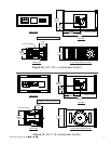
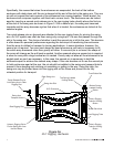
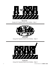
enclosure shell. Figure 3 illustrates the XLC enclosure rigging hardware components. Figures 4a
and 4b show key dimensions for the rigging hardware.
At the front of the frame is a rectangular rigging tube. Captured inside the rigging tube is a rigging
connector called the button bar. The button bar is constructed from a high-strength aluminum
alloy. The button bar can slide out the top of the tube and be locked into position as shown in
Figure 2. The portion of the button bar sticking out the top would be inserted into the front rigging
tube of an enclosure above, linking the two enclosures together and forming a hinging point
between the two enclosures. The button bar can also be fully retracted inside the tube for
transportation.
Each button bar has two spring-loaded buttons that extend out of the bar. The front rigging tube
has two holes that lock the buttons from the bar in place. As shown in Figure 3, the bottom button
locks the button bar in place at the top of the tube. The exposed top button is then used to lock
the button bar in the tube of an enclosure above. For transportation, the button bar would be slid
down inside the tube and would be locked in the tube using the top button.
At the rear of the frame is a rigging slot. Captured inside the rigging slot is a rigging connector
called the swing arm. The swing arm is constructed from a high-strength aluminum alloy. The
swing arm can be pivoted to stick out the top as shown in Figure 3. At the bottom of the frame, the
rear rigging slot has a series of holes.