


ELECTRO-VOICE
®
MAKE SURE THAT THE SPRING-LOADED BUTTONS ON THE BUTTON BARS
FULLY LOCK INTO THE ROUND HOLES IN THE FRONT RIGGING TUBES ON
BOTH ENCLOSURES. REPEAT THIS FOR EVERY ENCLOSURE ON BOTH
SIDES OF THE LINE ARRAY.
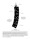
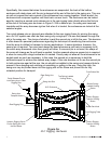
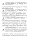
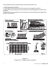
Attach the top enclosure in the array to the grid, as shown in Figure 6c. (Only an XLC compatible
grid can be used with an XLC array.) The grid has front rigging tubes just like the enclosures.
Slide the front button bar of the top enclosure into the front tube of the grid using the same tech-
nique that was used to link two enclosures.
MAKE SURE THAT THE SPRING-LOADED BUTTONS ON THE BUTTON BARS
FULLY LOCK INTO THE ROUND HOLES IN THE FRONT RIGGING TUBES ON
BOTH THE ENCLOSURE AND THE GRID.
The grid also has a rear rigging slot just like the enclosures, except that the grid only has one
attachment hole available. Unlock the rear swing arm from the top enclosure by removing the
quick-release pin from the rear rigging frame on the enclosure. Pivot the rear swing arm on the
enclosure up into the rear rigging slot on the grid. Insert the quick-release pin from the grid
through the holes in the rear rigging slot in the grid and through the slot in the swing arm. Repeat
the process for the other side of the enclosure and grid.
MAKE SURE THAT THE QUICK-RELEASE PIN IS FULLY LOCKED IN THE REAR
OF THE GRID AND THAT THE SWING ARM FROM THE ENCLOSURE IS
SECURED.
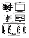
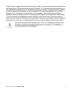
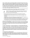
Now begin to lift the grid and the upper portion of the loudspeaker array, as shown in Figure 6d.
As the loudspeakers are lifted, the back corners of the loudspeaker enclosures will come together.
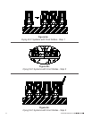
Pause when several loudspeakers are lifted off the ground. Unlock the rear swing arms on the
back of the enclosures by removing the quick-release pins in the frames. Pivot the rear swing
arms up into the rear rigging slots on the enclosures above, as shown in Figure 6e. Insert the
quick-release pin into the hole on the upper enclosure that will give the desired vertical splay
angle and through the slot on the swing arm. Make sure that the quick-release pin on the upper
enclosure is fully locked in the rigging frame and that the swing arm is fully secured. Repeat this
process for all the suspended enclosures on both sides of the array.
ON EACH ENCLOSURE, ALWAYS MAKE SURE THAT THE LEFT AND RIGHT
SWING ARMS ON THAT ENCLOSURE ARE LOCKED INTO THE SAME HOLES
FOR THE SAME VERTICAL SPLAY ANGLE. THE QUICK-RELEASE LOCKING
PINS ARE TETHERED TO THE REAR RIGGING FRAME WITH A LANYARD. THE
QUICK-RELEASE PINS MUST ONLY BE LOCKED IN THE REAR RIGGING
HOLES ON THE FRAME TO WHICH IT IS TETHERED. NEVER USE THE PINS
FROM ONE ENCLOSURE TO LOCK INTO ANOTHER ENCLOSURE.
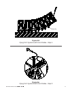
Remove the front dollies from the suspended enclosures. Grab the clips on the sides of the dollies
and pull them away from the sides of the enclosures until they unlatch from the rigging frame.
Continue lifting the array until additional enclosures are suspended. Then pause again and repeat
the process as described above. Continue this procedure until all the loudspeakers are rigged at
the back.
11