


ELECTRO-VOICE
®
6
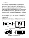
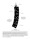
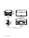
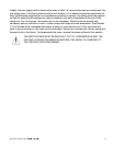
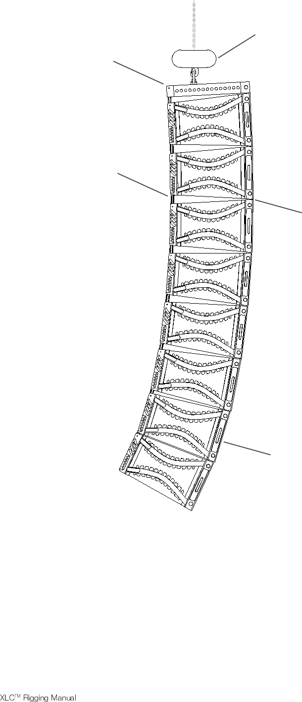
Figure 2:
Typical XLC Flying System
Hoist Motor
XLC Enclosures
Grid
Eight XLC Enclosures
Hinged at the Front by
the Button Bars and
Front Rigging Tubes
Angles Between
Enclosures fixed by Pins
through the Swing Arms
and Rear Rigging Slot
Holes
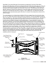
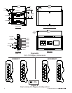
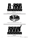
The swing arm from an enclosure below can be pivoted up so that one of the quick-release pins
may be inserted through the holes in the rigging slot on the frame and the slot in the swing arm,
linking the two enclosures together. The vertical tilt angle of the bottom enclosure is then
determined by the hole in which the swing arm is pinned. The XLC-127 and XLC-127+ enclosures
may be angled from 0° to 8° in 1° increments, while the XLC-118 enclosure may be angled from
0° to 12° in 1° increments. The angle adjustment holes are detailed in figures 4a and 4b. This pin
fixes the maximum distance the back corners of the enclosures may be separated.
Swing Arm
Button Bar