


ELECTRO-VOICE
®
19
The reader should consult an experienced structural engineer to perform the complex structural
analysis.
WHEN SUSPENDING ANY XLC LOUDSPEAKER SYSTEM OVERHEAD, THE
WORKING-LOAD LIMITS MUST NEVER BE EXCEEDED FOR EACH INDIVIDUAL
RIGGING POINT, AND THE OVERALL ENCLOSURE.
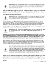
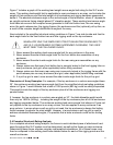
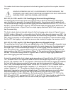
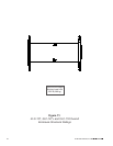
XLC-127, XLC-127+ and XLC-118 Front Rigging Structural-Strength Ratings
The working-load limit of each of the front rigging points on the XLC enclosures is dependent
upon the button bar assembly, the rigging frame assembly, the enclosure and the angle of pull.
The structural-strength ratings for the front rigging points are identical for the XLC-127, XLC-127+
and XLC-118, and are shown in Figure 8. The enclosures have two rigging points at the front. The
structural ratings shown in Figure 8 are for a single rigging attachment point. Each rigging point
has the same rating
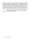
The front-to-back structural-strength ratings for the front rigging points shown in Figure 8 cover a
full 360° rotation. Although it is not possible to put the front button bars into tension over 360°, it is
possible for the button bars to go into compression with some array configurations. Therefore, the
360° rating is necessary to accommodate both tension and compression. It also should be noted
that the XLC front rigging is only rated for use over side-to-side pull angles of a maximum of ±10°.
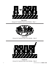
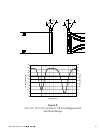
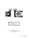
XLC-127, XLC-127+ and XLC-118 Rear Rigging Structural-Strength Ratings
The working-load limit of each of the rear rigging points on the XLC enclosures is dependent upon
the swing arm assembly, the rigging frame assembly, the quick-release pins, the enclosure and
the angle of pull. The structural-strength ratings for the rear rigging points are identical for the
XLC-127 and XLC-127+, and are shown in Figure 9. The structural-strength ratings for the rear
rigging points on the XLC-118 are shown in Figure 10. The enclosures have two rigging points at
the rear. The structural ratings shown in Figures 9 and 10 are for a single rigging attachment
point. Each rigging point has the same rating
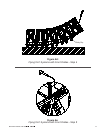
It should be noted that the front-to-back-angle range shown in Figure 9 for the XLC-127 and XLC-
127+ consists of two 8° arc segments, while the front-to-back-angle range shown in Figure 10 for
the XLC-118 consists of two 12° arc segments. When both the front and rear rigging are installed,
the front button bar always prevents the rear swing arm from having any kind of front-to-back
force. Thus, it will always be axially loaded. For the XLC-127 and XLC-127+, a tensile force can
only be applied over an angle range of negative 0°-8°, while the XLC-118 can only be over a
range of negative 0°-12°. The angles are negative because the boxes can only be angled
downward. (Imagine two boxes facing straight ahead. The bottom enclosure can only be tilted
downward because the rear rigging can only be adjusted to bring the rear corners of the
enclosures together.) Under compression, the forces would be from positive 172°-180° for the
XLC-127,and XLC-127+ and positive 168°-180° for the XLC-118. It also should be noted that the
XLC rear rigging is only rated for use over side-to-side pull angles of a maximum of ±5°.