


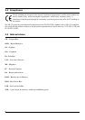
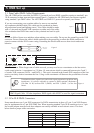
5.1 Data Cable (DMX Cable) Requirements:
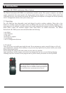
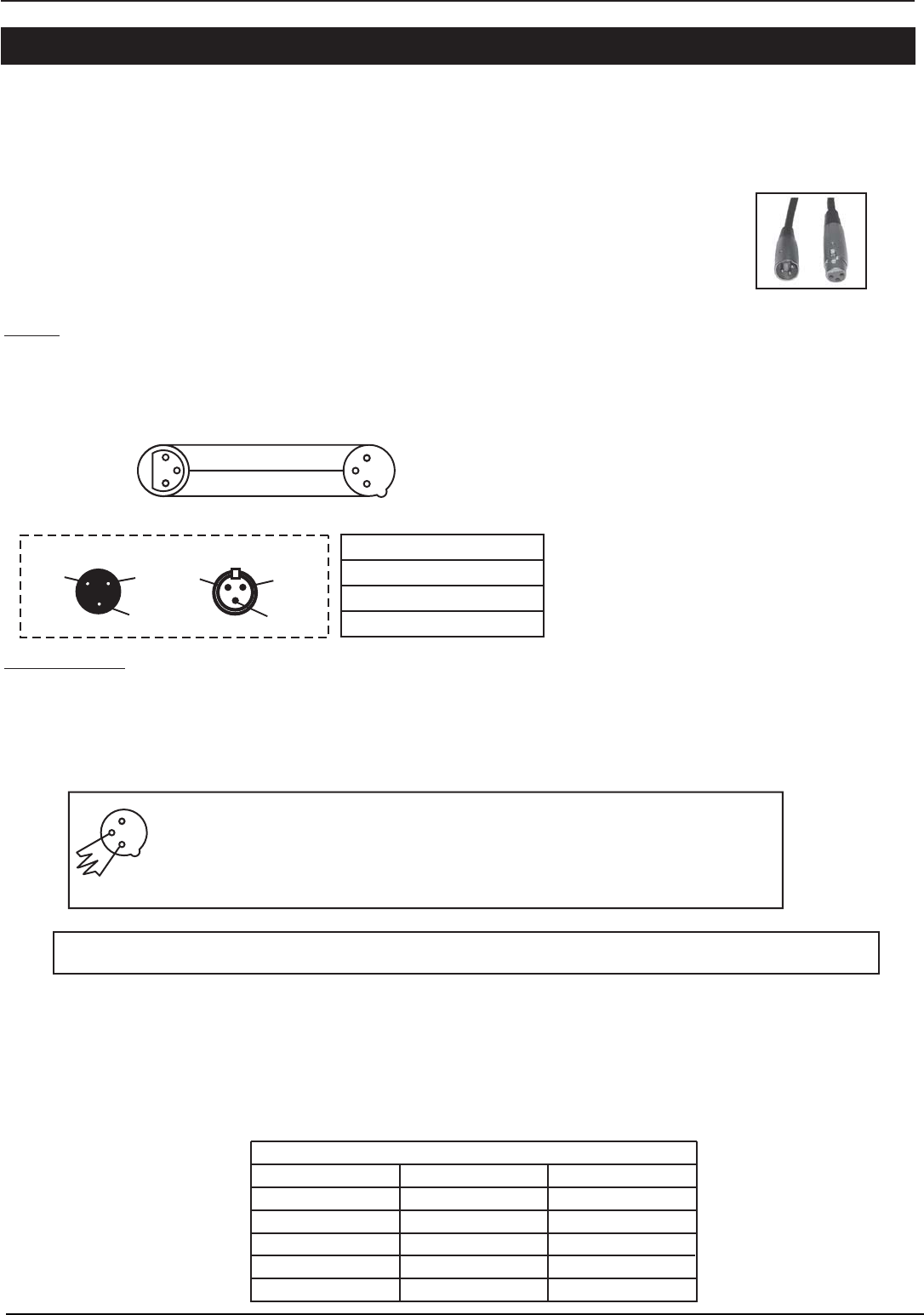
The AR-32RM can be controlled via DMX-512 protocol and your DMX controller requires a standard 3-pin
XLR connector for data input and data output(Figure1). Connect the AR-32RM and your fixtures together
using standard 3 pin DMX cables. The AR-32RM uses DMX-512 protocol to operate your fixtures.
If you are constructing your own data cables, be sure to use standard
two conductor shielded cable (This cable may be purchased at almost
all professional sound and lighting stores). Your cables should be made
with a 3-pin male and female XLR connector on either end of the cable.
Also remember that DMX lines must be daisy chained and can't be split.
Figure 1
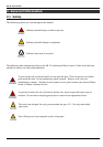
*Note:
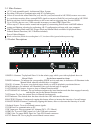
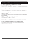
Be sure to follow figures two and three when making your own cables. Do not use the ground lug on the XLR
connector. Do not connect the cable's shield conductor to the ground lug or allow the shield conductor to
come in contact with the XLR's outer casing. Grounding the shield could cause a short circuit and erratic
behavior.
Figure 2
DMX512OUT
3-PINXLR
DMX512IN
3-PINXLR
COMMON
DMX+
DMX-
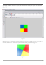
Figure 3
XLRMaleSocket XLRFemaleSocket
1Ground
2Cold
3Hot
3Hot
2Cold
1Ground
XLRPinConfiguration
Pin1= Ground
Pin2= DataCompliment(negative)
Pin3= DataTrue(positive)
*Special Note:
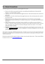
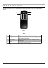
Line Termination. When longer runs of cable are used, you may need to use a terminator on the last unit to
avoid erratic behavior. A terminator is a 120 ohm 1/4 watt resistor which is connected between pins 2 and 3
of a male XLR connector (DATA + and DATA -). This unit is inserted in the female XLR connector of the last
unit in your daisy chain to terminate the line. Using a cable terminator will decrease the possibilities of erratic
behavior.
Termination reduces signal errors and avoids signal transmission problems and
interference. It is always advisable to connect a DMX terminal, (Resistance
120 Ohm 1/4 W) between PIN 2 (DMX-) and PIN 3 (DMX +) of the last
fixture.
Figure 4
1
2
3
DMX Signal Cable. 120 ohm impedance DMX signal cable MUST be used for signal connection.
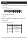
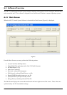
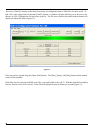
3-Pin XLR to 5-Pin XLR Conversion
Conductor
Ground/Shield
Data Compliment(-signal)
Data True(+signal)
Not Used
Not Used
3-Pin XLR Female(Out)
Pin 1
Pin 2
Pin 3
5-pin XLR Male(In)
Pin 1
Pin 2
Pin 3
Pin 4 - Do Not Used
Pin5-DoNotUsed
5.2 5-Pin XLR DMX Connectors.
Some manufactures use 5-pin XLR connectors for DATA transmission in place of 3-pin. 5-pin XLR fixtures
may be implemented in a 3-pin XLR DMX line. When inserting standard 5-pin XLR connectors in to a 3-pin
line a cable adaptor must be used, these adaptors are readily available at most electric stores. The chart
below details a proper cable conversion.
5. DMX Set up
11
Table 3