


PAGE 25
SPECIFICATIONS ARE SUBJECT TO CHANGE WITHOUT NOTICEDMS3040/3080/3120
INSTALLATION AND WIRING
MOH CONNECTIONS
3120 MOH Zone 1
AWG 18 TWISTED PAIR
MOH
Input
600
Ohm
Telephone System
KSU
600 ohm MOH System
Telephone
MOH OTPUT LEVEL CONTROL
2
3
4
SER. NO.
CLASS 2 WIRING ACCEPTABLE
COM 8 25V 70V
SPEAKER OUTPUT
GROUND
LINE FUSE
5A 250V
117V 500W MAX
117V 60HZ
LEVEL
LEVEL
VOX-1
UNSWITCHED
0 600
ZONE 2
ZONE 1
0 8
0 8
SENS
ZONE 2
ZONE 1
POWER RATING
SUPPLY VOLTAGE
POWER CONSUMPTION
DIGITAL MUSIC AMPLIFIER
CAUTION: TO REDUCE THE
RISK OF FIRE, REPLACE
ONLY WITH SAME TYPE
FUSE.
MOH OUT
BALANCED
PROFESSIONAL AUDIO & SOUND
1 WATT
1 WATT
MODULE
JUMPER
SW702
AUX 1
AUX 2
MOH - ZONE 1
INPUT SOURCE
DEFAULT JUMPER
SETTING
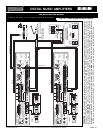
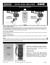
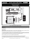
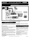
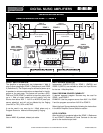
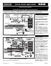
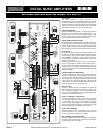
Fig. 25 - Rear Panel MOH Connection Diagram
MOH/ZONE 1 AMPLIFIER SOURCE SELECTOR
MOH AMPLIFIER
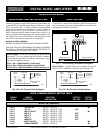
An independent 600 ohm, 1 Volt Output, Transformer Balanced
MUSIC-ON-HOLD Amplifier is provided. The Input SOURCE of the
MOH Amplifier can be selected from either the AUX 1 - AUX 2 or MOD-
ULE.
MOH - 600 OHM SYSTEM
Most Phone systems operate on a 600 ohm Input Impedance, if the
Impedance required is 600 ohm connect the Amplifier to the Phone
System MOH by using the diagram above (Reference 3).
MOH - 8 OHM, 1 WATT SYSTEM
Some older Key Phone systems require a 1 watt Power Output having
an Output Impedance of 8 ohm to drive the Music on Hold feature. If
the Impedance required is 8 ohm connect the Phone system MOH to
the 8 ohm, 1 Watt MOH Output of the Amplifier (Reference 4).
CABLE
Use a cable consisting of a twisted pair of at least AWG 18. Use care
in extending the cable and avoid routing near power lines, fluorescent
lights and other systems that may generate a disturbing electric field.
SOURCE SELECTOR
Select the Input Source desired by following the instructions at right.
CAUTION: REMOVAL OF THE COVER PRESENTS AN ELECTRI-
CAL SHOCK HAZARD !
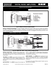
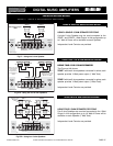
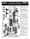
MUSIC ON HOLD AMPLIFIER
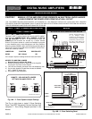
MOH/ZONE 1 SOURCE SELECTOR
The Source for the MOH/ZONE 1 Amplifier can be selected
from either the AUX 1 - AUX 2 or MODULE by setting the
JUMPER SET No. SW702 provided for this purpose. Default
Setting for this Jumper Set is AUX 1. To change the setting do
the following:
ACCESS TO THE MOH/ZONE 1 INPUT SOURCE SETTING
1) Remove Power Cord from AC Outlet.
2) Remove the three screws on each side of the amplifier
holding the amplifier cover.
3) Lift Cover and locate the Jumpers Set No SW702 on the
MOH Amplifier Board (see Function Switches Jumpers
Location Diagram).
4) Set Jumper as required (AUX 1 - AUX 2 or MODULE)
5) Replace protective cover.
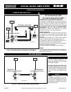
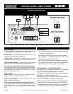
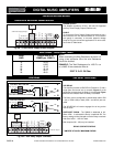
LEVEL CONTROL
After the wiring is completed adjust the MOH/ZONE 1
Amplifier Level Control on the rear panel to the desired output
level (Reference 2).
PROFESSIONAL AUDIO & SOUND
®
TM
DIGITAL MUSIC SERIES
DIGITAL MUSIC AMPLIFIERS