


PAGE 17
SPECIFICATIONS ARE SUBJECT TO CHANGE WITHOUT NOTICEDMS3040/3080/3120
ADDRESSABLE DUAL MUTING SYSTEM
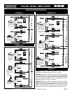
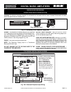
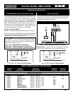
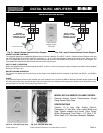
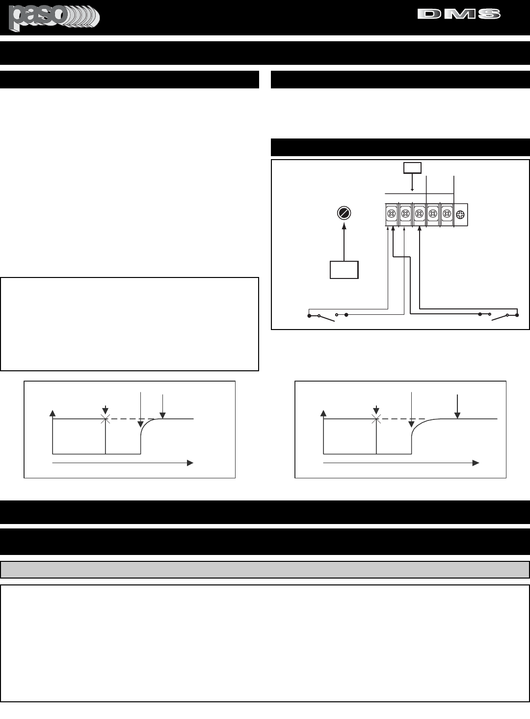
DIRECT MUTING - Direct Muting may be accomplished by short-
ing the MUTE 1 and MUTE 2 Terminals to the G Terminal through
an external switch. Each time the Muting Switch is closed the cor-
responding MUTE BUSS is activated.
Fig. 17 - Direct Muting Terminals and Diagram
DIRECT MUTING
WIRING
3120 M1 - M2 01
GM2
M1 RVC
GROUND
MUTE 1
MUTE 2
MASTER
REMOTE
VOLUME
RVC
MUTING SWITCH M 2
MUTING SWITCH M 1
10
31
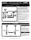
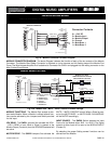
MUTE-2
DELAY
Signal
Level
Program
gradually
restored
2-3
sec.
Mute terminals
opened
time
DMS mutfunct 01
Program
Attenuation
60 dB
MUTE 1
Terminals
shorted
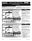
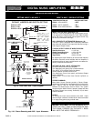
Fig. 17B - M 1 Function Timing Diagram
MUTING TIMING - The MUTING is preset for -60 db Attenuation.
When MUTE 1 or 2 are activated the MUTE BUSS is instanta-
neously Switched-ON. When the Muting is deactivated the pro-
gram source is gradually restored.
MUTE 1 (M1) = TIMING PRESET 2-3 SECONDS
MUTE 2 (M2) = TIMING ADJUSTABLE 3-30 SECONDS
MUTE 2 DELAY = USE REAR PANEL CONTROL Reference 31
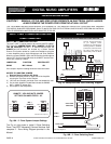
INSTALLATION AND WIRING
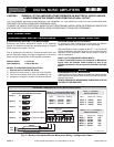
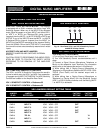
MUTE JUMPERS DEFAULT SETTING TABLE
SW206 VOX RELAY - MUTE 1 - MUTE 2 M1
SW216 TEL IN - MUTE 1 - MUTE 2 - OFF OFF
SW217 INPUT 4/AUX 1 - MUTE 1 - MUTE 2 - OFF M1
SW218 INPUT 3 - MUTE 1 - MUTE 2 - OFF OFF
SW219 INPUT 2 - MUTE 1 - MUTE 2 - OFF OFF
SW220 INPUT 1 - MUTE 1 - MUTE 2 - OFF OFF
SW222 MODULE - MUTE 1 - MUTE 2 - OFF OFF
SW223 INPUT 5/AUX 2 - MUTE 1 - MUTE 2 - OFF M1
SW227 CHIME TRIGGER - MUTE 1 - MUTE 2 M1
JUMPER JUMPER FUNCTION FACTORY FACTORY
ID NO. REFERENCE DESCRIPTION SETTING SETTING
MAIN PCB JUMPERS
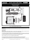
DUAL MUTING SYSTEM - The Amplifier is equipped with a DUAL
noiseless, fast acting Logic MUTING Switching System. When any
of the INPUTS are activated and a Signal is present on a given
INPUT and either VOX 1 or VOX 2 or BOTH are Switched-ON
(using internal Jumpers) then the MUTE 1 or MUTE 2 BUSS or
BOTH are ACTIVE. If any of the INPUTS have the MUTE 1 or
MUTE 2 Switched-ON (by Internal Jumpers) then the INPUT (or
INPUTS) will be MUTED according to the Jumpers Setting. Once
the SIGNAL-ON on the ACTIVE INPUT is terminated the normal
functions are automatically restored on all muted inputs.
ACCESS TO MUTE JUMPERS
REFER TO JUMPERS AND SWITCHES INTERNAL ACCESS.
CAUTION: PRIOR TO PERFORMING THE ABOVE OPERATION
BE SURE TO FOLLOW THE SAFETY NOTES REFERRING TO
THE REMOVAL OF THE AMPLIFIER COVER.
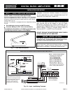
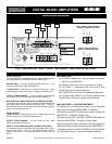
Signal
Level
MUTE 2
Terminals
shorted
Program
gradually
restored
Adjustable
from
3 to 30
seconds
Mute terminals
opened
time
DMS mutfunct 02
Program
Attenuation
60 dB
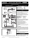
Fig. 17C - M 2 Function Timing Diagram
MUTE 2 DELAY - The M 2 Delay can be adjusted by using the
MUTE 2 DELAY CONTROL
on the rear panel (reference 31).
PROFESSIONAL AUDIO & SOUND
®
TM
DIGITAL MUSIC SERIES
DIGITAL MUSIC AMPLIFIERS