


PAGE 11
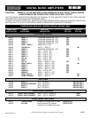
SPECIFICATIONS ARE SUBJECT TO CHANGE WITHOUT NOTICEDMS3040/3080/3120
INSTALLATION AND WIRING
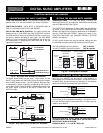
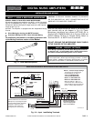
USING A PUSH-TO-TALK DESK BASE MICROPHONE
Microphone paging and precedence over AUX 1 or AUX 2 channels
may be accomplished by using a Desk Base or a Gooseneck
Microphone. Wire the Microphone output leads to the MIC input ter-
minals as per Fig. 11A.
MUTING: The Amplifier is equipped with two independent Muting
Circuits:
z Direct Muting by shorting the MUTE Terminals
z
Automatic Muting with VOX - Voice Activated Muting
For additional information on the Muting operation refer
to the Muting Functions section of this Manual.
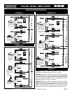
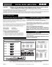
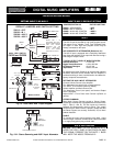
WIRING
3120 Micbase 01
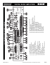
INPUT 1 - Default Jumper Settings
INPUT 3 (MIC)
INPUT 2 (MIC)
INPUT 1 (MIC)
G COM HOT G COM HOT G COM HOT
BALANCED
250ohm 1.5mV
The Diagram at Left shows the
Default Settings for INPUT 1.
VOX 1 is SWITCHED ON
VOX 2 is SWITCHED OFF
MUTE 1 is SWITCHED OFF
MUTE 2 is SWITCHED OFF
When the INPUT 1 (MIC 1) is
activated the VOX 1 BUSS is ON
and it will MUTE any Input with the
MUTE 1 Setting SWITCHED ON.
NOTE: To change the
INPUT Default Settings
refer to the appropriate
section in this Manual
V1
V2
OFF
VOX 1 BUSS
ACTIVATED
VOX 2 BUSS OFF
M2
M1
OFF
INPUT 1
X
MUTE 2 BUSS OFF
X
X
MUTE 1 BUSS OFF
AUDIO OUT
MIC IN
VOX SEND
MUTE RECEIVE
SW215
SW220
=
JUMPER
JUMPER
JUMPER
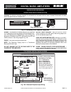
VOX - MUTE JUMPERS SETTING
GM2
M1 RVC
GROUND
MUTE 1
MUTE 2
MASTER
REMOTE
VOLUME
RVC
SHIELD
MIC
Lo Z
B
A
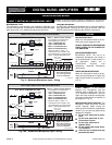
MUTING SWITCH
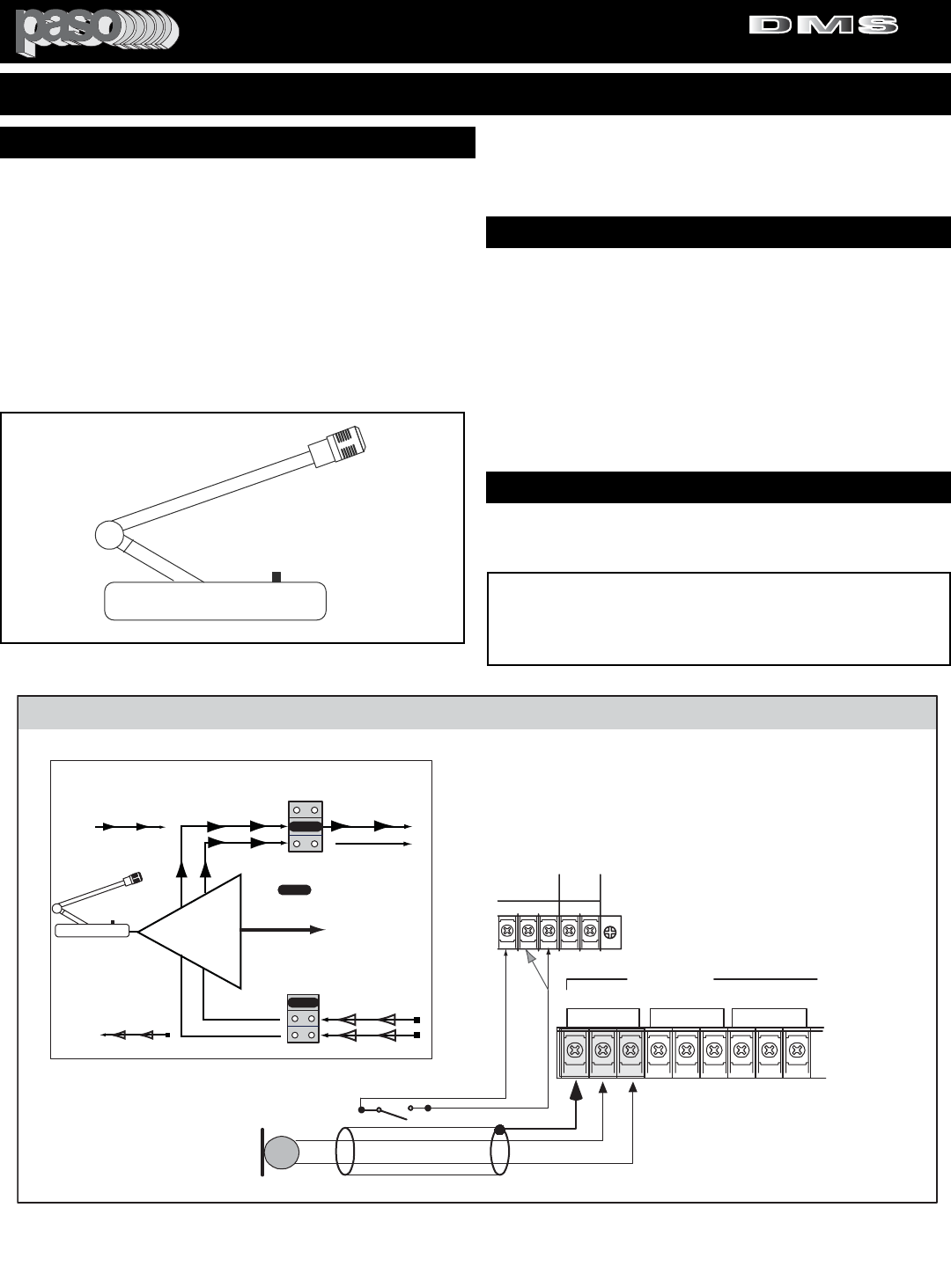
Connect Desk Base or Gooseneck
Microphone as per diagram below.
Connect Muting Switch to MUTE 1
or MUTE 2 and G Terminals.
If using the VOX system the
muting switch is unnecessary.
Push to Talk Key
DESK BASE/GOOSENECK MICROPHONE WITH MUTING SWITCH
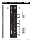
Fig. 11A - Input 1 and Muting Terminals
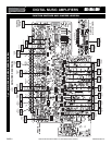
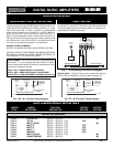
Wire the Desk Base Microphone leads to the Microphone
Input terminal strip as per diagram in Fig 11A. Check
Microphone instructions and connect HOT LEAD (B) to
Terminal HOT, COMMON LEAD (A) to Terminal COM and
SHIELD LEAD to Terminal G. Connect Muting Switch to
Terminals MUTE 1 or MUTE 2 and G as shown.
DO NOT GROUND THE MICROPHONE CABLE SHIELD
TO THE CHASSIS OF THE AMPLIFIER
b50side
b50side
Push to Talk Key
Push to Talk Key
Fig. 11 - Desk Base Microphone
INPUT 1 - USING A DESK BASE MICROPHONE
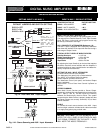
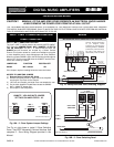
MUTING - PRIORITY SETTINGS
MUTING INPUT 4/AUX 1 (MUSIC INPUT)
To mute Input 4/AUX 1 (Music Input) when Paging from MIC 1, set INPUT
4/AUX 1 MUTE 1 JUMPER to ON Position. Each time MIC 1 is activated
the Program on Input 4/AUX 1 is automatically muted by the VOX.
Direct Muting is provided by the Desk Base Muting Switch wired as
per diagram in Fig. 11A. If Auto-Mute (VOX) is desired follow instruc-
tions below.The Desk Base Muting Switch can be omitted.
CAUTION:
TO PREVENT POSSIBLE DAMAGE TO SPEAKERS
OR THE AMPLIFIER ALL INPUT CONNECTIONS MUST BE
MADE WITH THE AMPLIFIER POWER OFF.
PROFESSIONAL AUDIO & SOUND
®
TM
DIGITAL MUSIC SERIES
DIGITAL MUSIC AMPLIFIERS