


PAGE 13
SPECIFICATIONS ARE SUBJECT TO CHANGE WITHOUT NOTICEDMS3040/3080/3120
3120 Telpaging 01
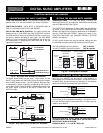
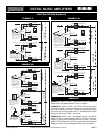
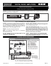
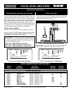
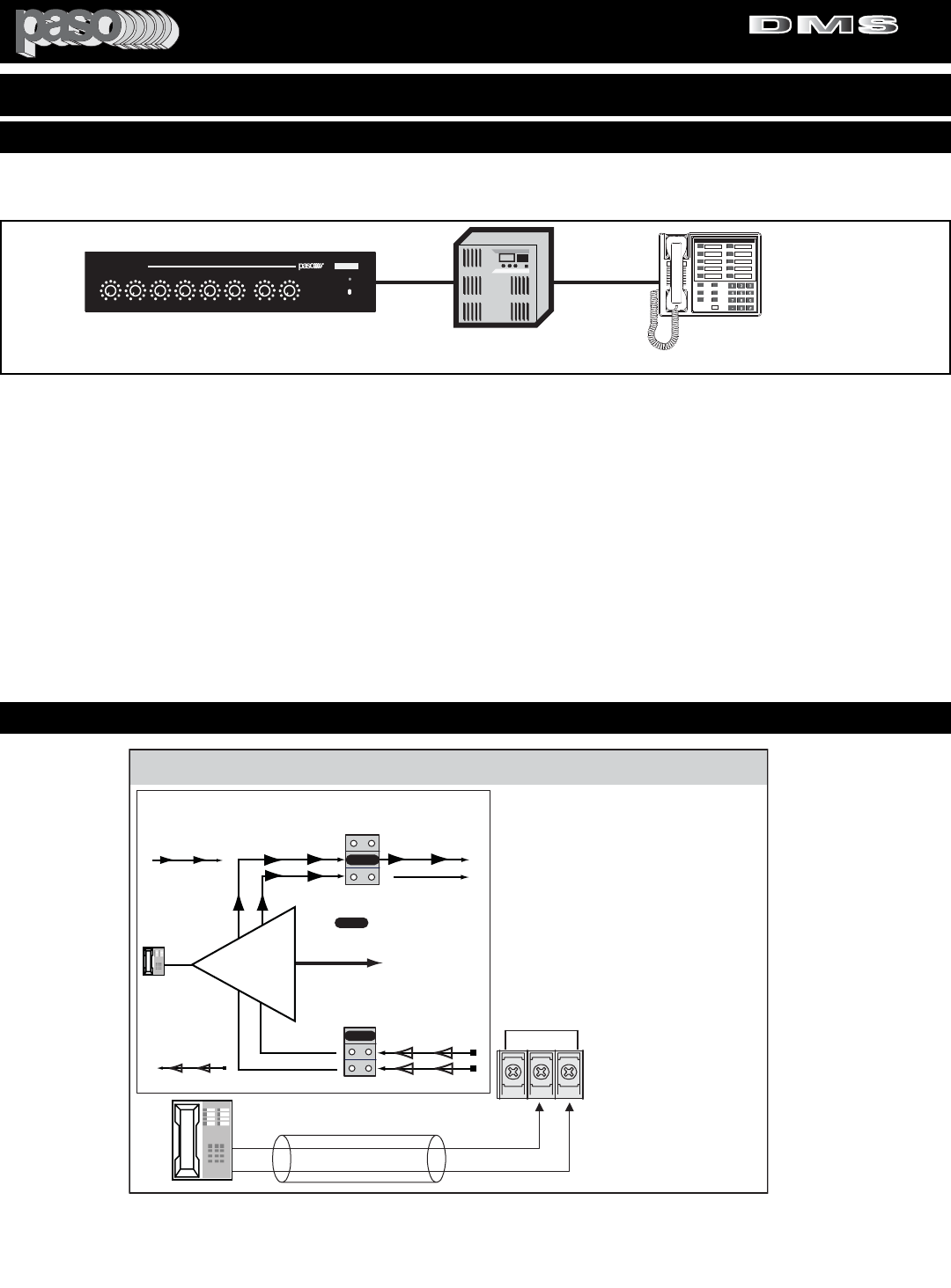
BALANCED TELEPHONE PAGING WIRING
TIP
RING
TEL INPUT - Default Jumper Settings
TEL
G COM HOT
BALANCED
600 ohm 100 mV
The Diagram at Left shows the
Default Settings for TEL INPUT.
VOX 1 is SWITCHED ON
VOX 2 is SWITCHED OFF
MUTE 1 is SWITCHED OFF
MUTE 2 is SWITCHED OFF
When the TEL INPUT (PHONE) is
activated the VOX 1 BUSS is ON
and it will MUTE any Input with the
MUTE 1 Setting SWITCHED ON.
NOTE: To change the
INPUT Default Settings
refer to the appropriate
section in this Manual
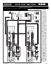
Telephone System
Paging Output
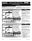
V1
V2
OFF
VOX 1 BUSS
ACTIVATED
VOX 2 BUSS OFF
M2
M1
OFF
X
MUTE 2 BUSS OFF
X
X
MUTE 1 BUSS OFF
PAGING OUT
VOX SEND
MUTE RECEIVE
SW214
SW216
=
JUMPER
TEL INPUT
TEL IN
JUMPER
JUMPER
JUMPER
VOX - MUTE JUMPERS SETTING
Fig. 13A - Balanced Telephone Input Wiring
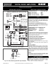
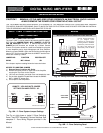
WIRING - The Amplifier is interface ready for the Telephone
line in applications requiring paging from the telephone sys-
tem. The Telephone line Paging Output (Tip and Ring) can
be directly connected to the TEL input and to the HOT and
COM as shown in the wiring diagram Fig. 12A
.
CABLE - Use a two conductor twisted wire.
NOTE: The Telephone Paging Input is a Transformer
Balanced 600 ohm input.
DO NOT GROUND THE TIP OR RING WIRE TO THE
CHASSIS OF THE AMPLIFIER
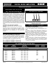
OUTPUT LEVEL CONTROL - Use TEL OUTPUT LEVEL
Control located on the Rear panel. After wiring adjust con-
trol for the desired output level.
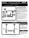
VOICE ACTIVATED MUTING (VOX) - Muting of the AUX 1
channel (music muting) during Paging is automatic via the
Voice Activated Muting System. No contact closure for the
Muting Circuit is required from the Telephone system. For
additional information on the Muting operation refer to the
Muting Functions section of this Manual.
PHONE PAGING PRIORITY OVER MICROPHONES -
Priority over any Microphone Input may be accomplished by
setting the MIC Inputs MUTE Jumpers.
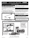
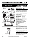
KSU
Key Service Unit
telpagin
Telephone
DMS Amplifier
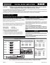
DIGITAL MUSIC AMPLIFIER
O
POWER
PROFESSIONAL AUDIO & SOUND
DIGITAL MUSIC SERIES
TM
OUTPUT LEVEL
PEAK
INPUT 1 INPUT 2 INPUT 3 INPUT 4/AUX 1 INPUT 5/AUX 2 BASS TREBLEMODULE
100 100 100 100 100 100 +10-10 +10-10
DMS
TEL
INSTALLATION AND WIRING
Fig. 13 - Connecting to the Telephone Paging KSU
CAUTION:
TO PREVENT POSSIBLE DAMAGE TO SPEAKERS OR THE AMPLIFIER ALL INPUT CONNECTIONS MUST BE MADE
WITH THE AMPLIFIER OFF (POWER OFF).
PAGING FROM THE TELEPHONE SYSTEM
TELEPHONE SYSTEM PAGING WIRING
PROFESSIONAL AUDIO & SOUND
®
TM
DIGITAL MUSIC SERIES
DIGITAL MUSIC AMPLIFIERS