


PAGE 18
SPECIFICATIONS ARE SUBJECT TO CHANGE WITHOUT NOTICE DMS3040/3080/3120
INSTALLATION AND WIRING
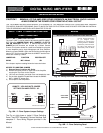
INPUT 1 (MIC 1) UNMUTING FUNCTION
The Input 1 (MIC 1) can be preset to be normally MUTED (INPUT
OFF) when the JUMPER SW205 - MIC 1 UNMUTE - IS SET TO
THE ON POSITION. The MIC 1 is SWITCHED-ON when the
UNMUTE and G Terminals are shorted by a Switch Contact
Closure. This function allows for a multi zone installation using two
or more Amplifiers and a single Microphone and Zone Switches.
When the Jumper SW205 is set to the ON Position the Microphone
Input is OFF and it is turned ON when the UNMUTE and the G ter-
minals are closed by a switch.
JUMPER NO. FUNCTION POSITION SET
SW205 MIC 1 Muted ON
If the Jumper requires resetting follow the instruction below.
ACCESS TO UNMUTING JUMPER
1) Remove Power Cord from AC Outlet.
2) Remove the three screws on each side of the Amplifier
securing the Top Cover to the Chassis.
3) Lift Cover and carefully and slide Cover out towards the rear.
4) On the Main Amplifier Printed Board locate the SW205 -
MIC 1 UNMUTE Jumper Set.
5) Set Jumper to the ON position.
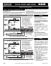
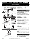
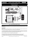
Fig. 18 - Microphone and Zone Unmuting Diagram
THE FOLLOWING INSTRUCTIONS REQUIRE THE REMOVAL OF THE AMPLIFIER PROTECTIVE COVER AND ARE PROVIDED
FOR USE BY QUALIFIED PERSONNEL ONLY.TO AVOID THE RISK OF ELECTRICAL SHOCK DO NOT PERFORM ANY INSTALLA-
TION OR SERVICING UNLESS YOU ARE QUALIFIED TO DO SO.
CAUTION ! REMOVAL OF THE AMPLIFIER COVER PRESENTS AN ELECTRICAL SHOCK HAZARD
ALWAYS REMOVE THE POWER CORD FROM THE AC WALL OUTLET
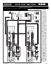
DIRECT UNMUTING
WIRING
3120 Unmute 01
INPUT 2 (MIC)
INPUT 1 (MIC)
G COM HOT G COM HOT
BALANCED
250ohm 1.5mV
SHIELD
MIC
Lo Z
B
A
ZONE UNMUTING SWITCH
Connect Paging Microphone
as per diagram below
(reference 30). Connect Zone
Unmuting Switch to UNMUTE
(reference 9) and G Terminals.
The VOX (if ON) feature will
automatically mute the Music
MICROPHONE WITH UNMUTING ZONE SWITCH
9
30
MIC1 G M2
M1 RVC
GROUND
UNMUTE
MUTE 1
MUTE 2
MASTER
REMOTE
VOLUME
RVC
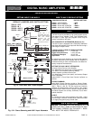
A = Common
B = Hot
OFF
SW215
JUMPER
VOX 1 ON
INPUT 1
MIC 1
V1
V2
SW205
OFF
JUMPER
On
MIC 1
UNMUTE
OFF
MUTE 1 ON
SW217
JUMPER
INPUT 4
AUX 1
M1
M2
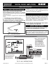
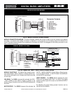
UNMUTE - VOX AND MUTE JUMPER
SETTINGS ON AMPLIFIERS 1 & 2
3120 Unmute Jump Set
Fig. 18A - 2 - Zone System Jumper Settings
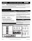
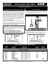
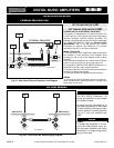
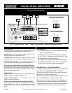
21
ZONE 1
2 - ZONE
PAGING SELECTORS
ZONE 2
PAGING MICROPHONE
TO AMP 1
TO AMP 2
3120 2 Zone Diagram 01
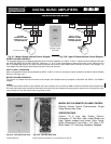
TO MIC INPUT
SPST ZONE
SWITCHES
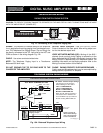
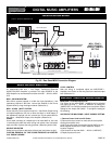
Fig. 18B - 2 - Zone Switching Panel
INPUT 1 (MIC 1) UNMUTING FUNCTION
The Fig. at right shows a typical 2 Zone Switching
Panel. Use SPST Momentary Contact Switches. See
complete 2 - Zone Wiring Diagram provided in this
Manual.
PROFESSIONAL AUDIO & SOUND
®
TM
DIGITAL MUSIC SERIES
DIGITAL MUSIC AMPLIFIERS