


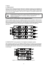
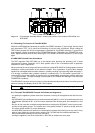
11. Ground Lift Switch CIRCUIT ⊥ TO CHASSIS SWITCH
Using the ground lift switch CIRCUIT ⊥ TO CHASSIS SWITCH (22) lets you separate the audio signal
ground from the enclosure ground (safety earthing). This helps to solve problems with hum or noise without
jeopardizing safety standards. If several units with ground lift switch are installed in a common enclosure
or rack system, it is recommended to set the ground lift switches of all devices but one to “ungrounded”.
Set to “ungrounded”, the impedance between signal ground and enclosure is: 100 k ohms // 100 nF. It is
necessary to maintain the immunity from EMV.
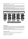
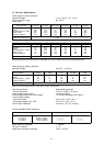
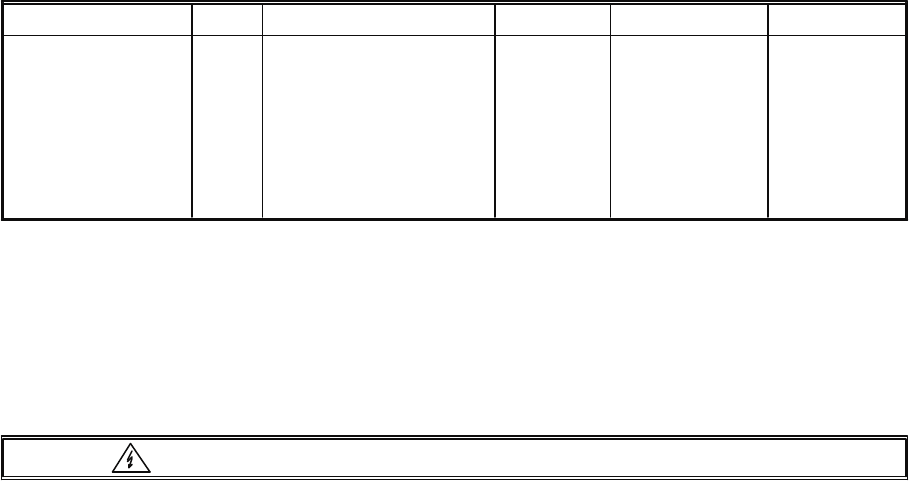
12. Fuses
Location Pos. Used for Value Dimensions Standard
Fuse switch (11)
Fuse switch (11)
Board 86243
Board 85272
Board 85272
Board 85272
Board 85272
Board 85272
Board 85272
F601
F601
F602
F502
F503
F504
F505
F506
F507
Mains fuse 230 V~ AC
Mains fuse 115 V~ AC
Mains fuse AC
Battery fuse 24 V DC
Battery fuse 24 V DC
Power-AMP 1
Power-AMP 2
Power-AMP 3
Power-AMP 4
T4AL 250V
T8AH 250V
T1AL 250V
25AL 32V
25AL 32V
T6.3AL 250V
T6.3AL 250V
T6.3AL 250V
T6.3AL 250V
5 x 20 mm
5 x 20 mm
8.5 x 8.45 mm
Flat type fuse
Flat type fuse
5 x 20 mm
5 x 20 mm
5 x 20 mm
5 x 20 mm
IEC 127
IEC 127
IEC 127
DIN 72581-3
DIN 72581-3
IEC 127
IEC 127
IEC 127
IEC 127
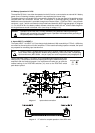
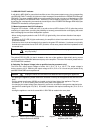
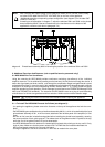
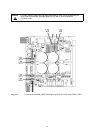
Changing The Fuses F502 And F503 (see diagram 11):
Caution Unplug the mains cord and disconnect batteries before opening the appliance!
The battery fuses F 502 and F503 are located on the mains (power supply) printed board assembly 85272
behind the AMP-battery connectors. In case they need to be replaced, commence as follows:
- open the appliance by removing the 9 screws that lock the cover-plate
- remove the mains input printed board assembly 86243 that is located at the rear inner wall.
Therefore, unplug the yellow/green ground conductor form the corresponding connector at the rear
inner wall. To remove the AMP-plug, press its lock-piece
- now, you have to remove the 3 screws of the mains-input printed board assembly 86243 marked “C”
(refer to the picture of the rear panel on page 21).
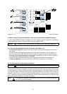
- disconnect the 6-pole flat cable between the two relays on the mains-input printed board assembly
86243 that is connected to the male multi-point connector B602
- now, the hinged mains-input printed board assembly 86243 can be turned up. In doing so, be careful
not to damage any wiring or other parts
- the fuses F502 and F503 are now easy to get to and can be removed to the top
- for re-installing the mains-input printed board assembly 86243, proceed in opposite order:
tighten the mains-input printed board assembly 86243 with the 3 screws marked “C”, where each,
the mains plug (10) and the mains selector switch (12) need to be connected using individual screws
and self-securing nuts M3.
- reconnect the 6-pole flat cable to the multi-point connector B602
- reconnect the yellow/green ground cord to the ground connector on the rear panel; make sure that it
sits tight
- closing the appliance: reattach the cover-plate with 9 screws M3 x 6 DIN 7500
33