


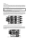
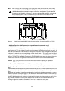
9.2.2 Checking The Function Of The NRS 90207:
With built-in NRS 90207 and powered-on amplifier, the READY-indicators (7) have to light. When using
an external switch to shortcut one pole of the 100 V speaker network via a 47 k ohms resistor and the
safety earthing conductor for approximately 5 seconds, the corresponding GROUND FAULT indicator (6)
has to light. The fault-message is transmitted to the PROMATRIX Manager DPM 4000 (see PROMATRIX
handbook). After releasing the external switch, indication and message have to stay present. Use the
TEST-button (3) to reset the ground fault surveillance function.
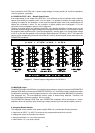
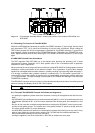
9.3 NRS 90208 Input Transformer For Floating, Balanced Inputs
In case floating inputs are needed, the inputs of the DPA 4411 are prepared for retrofitting input
transformers; a separate NRS 90208 extension-kit is needed per input.
Note If a switch-contact is located between the control amplifier output and the power amplifier
input, switch clicks might become audible during switching. If this is the case, incorporating
input transformers can solve the problem.
Caution Unplug the mains cord and disconnect batteries before opening the appliance!
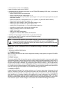
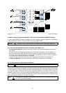
9.3.1 Retrofitting The NRS 90208 On The Printed Board Assembly 81331:
- for opening the appliance, please remove the 9 screws on the top of the appliance that lock the cover
plate
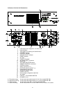
- detach the rear panel by removing the screws marked “A” to “D” (refer to the picture of the rear panel
on page 21).
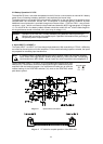
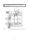
- remove the input printed board assembly 81331: (see diagram 10)
remove the 8 screws marked “D” that tighten the input sockets and detach the 6 flat cables CN1 to CN6.
For removing the printed board assembly 81331 you have to unscrew the two screws on the side panel
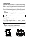
- before installing the input transformer, make sure to unsolder the resistors for T1: R1/R5, for T2:
R9/R13, for T3: R17/R21, for T4: R25/R29 and clean the corresponding eyelets
- place the input transformer onto the printed board assembly 81331, so that the markings on the board
and on the bottom part of the transformer are aligned. As a protection against short-circuit, place the
supplied insulating disk between the printed board and the transformer
- before re-installing the printed board assembly 81331, reconnect the flat cables CN1 to CN6. Keep in
mind that the plug of the cable leading to CN1 (AMP1+2) is marked. Now, reconnect the printed board
assembly 81331 to the amplifier’s side panel, using two screws M3 x 12
- installation of the rear panel:
first, connect the POWER OUTPUT printed board assembly to the rear panel, using two screws marked
“C”. Make sure not to squeeze any wires. Now, you can slide the rear panel underneath the four
lock-fish-plates of the input sockets. In doing so, mind that the acknowledge button of the ROUTING
switches need to be pulled through the corresponding openings
input sockets are tightened with two screws marked “D”, each
the power supply printed board assembly 85272 gets tightened using two screws marked “C”; mind the
acknowledge button of the CIRCUIT ⊥ TO CHASSIS SWITCH.
tighten the Remote Control printed board assembly with two screws marked “C”; mind the yellow
STATUS-LED
tighten the mains-input printed board assembly 86243 using three screws marked “C”; tighten the mains
connector (10) and the mains selector switch (12) with individual screws and self-securing nuts M3
reinstall the rear panel using 6 screws marked “A”
tighten the heat sink using four screws marked “B”
- closing the appliance: reconnect the cover-plate using 9 screws M3 x 6 DIN 7500
31