


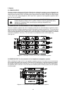
Note After changing the output voltage, use a waterproof marker pen to note the correct, newly
set value on the label-field OUTPUT VOLTAGE (20) on the rear of the appliance.
Additionally note the corresponding output configuration (see diagram 5) on the label OUT
CONFIG TYPE (20).
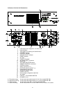
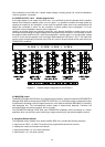
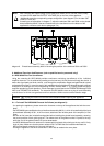
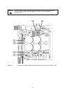
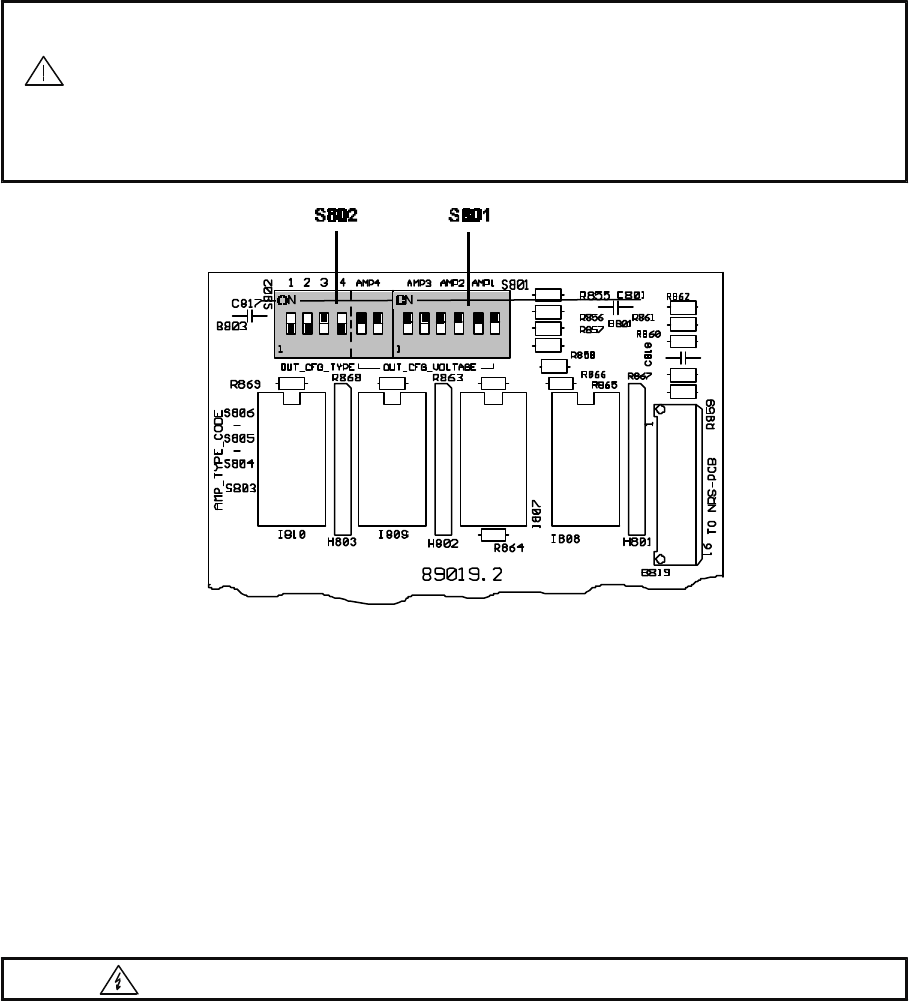
According to the description in diagram 7, adjust the switches S801 and S802 on the printed
board assembly 89019.2 that are located next to the transformers on the bottom of the
appliance’s enclosure (refer also to paragraph 5.4 ).
diagram 8 Printed board assembly 89019.2 showing the position of the switches S801 and S802
9. Additional Functions And Features (refer to qualified service personnel only!)
9.1 NRS 90206 Pilot Ton Surveillance
Using the extension-kit NRS 90206 provides continuous monitoring (surveillance) of the individual
amplifier channels. This is achieved by sending an ultra low-level 19 kHz pilot tone through the device. It
enters the signal path post level controls, runs through the amplification stages and gets filtered out and
evaluated at the output. In case the result of this evaluation shows that the pilot dropped beneath a defined
threshold or is missing at all, the corresponding READY indicator AMP 1 - 4 (7) goes out but the power
amplifier upholds its normal operation. A fault-message is transmitted to the PROMATRIX Manager DPM
4000 (see PROMATRIX handbook). The extension-kit NRS 90206 comes as a plug-in board assembly
and consists of a 19 kHz tone-generator and four selective 19 kHz receivers with evaluation stage.
Caution Unplug the mains cord and disconnect batteries before opening the appliance!
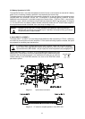
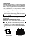
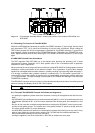
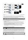
9.1.1 To Install The NRS 90206 Proceed As Follows (see diagram 9):
- for opening the appliance, please remove the 9 screws on the top of the appliance that lock the cover
plate.
- the NRS 90206 gets retrofitted on the printed board assembly 89019.1, which is located behind the input
printed board assembly 81331, in the front area, attached to the left side panel of the amplifier (in front
view).
- Be sure to first insert the included board-guides before installing the printed board assembly, assuring
the correct position of their guide grooves. The release lever of the guides marked “A” points to the top,
while the one of the guides marked “B” points downwards.
- the NRS 90206 extension-kit needs to be inserted with its printed side pointing to the top, until it firmly
locks in place. Make sure that the power resistors R917 to R920 that are located underneath the
NRS-printed board assembly do not touch this board.
- closing the appliance: use the 9 screws M3 x 6 DIN 7500 to reattach the cover plate.
29