


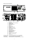
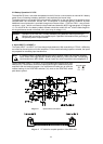
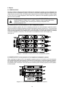
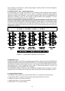
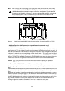
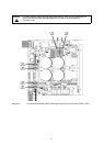
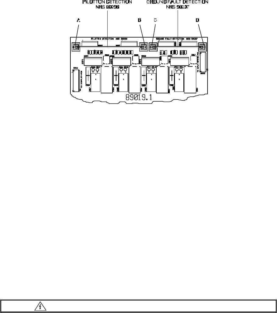
diagram 9 Printed board assembly 89019.1 showing the position of the modules NRS 90206 and
NRS 90207
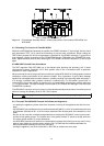
9.1.2 Checking The Function Of The NRS 90206:
With built-in NRS 90206 and powered-on amplifier, the READY-indicators (7) have to light. Use the check
and reset-button TEST (3) to check the functioning of the pilot tone surveillance. When holding the
TEST-button pressed, the 19 kHz tone-generator is switched off, the READY-indicators (7) go out and a
fault-message is being transmitted to the PROMATRIX Manager DPM 4000 (see PROMATRIX hand-
book). Approximately 3 seconds after releasing the TEST-button, the READY-indicators (7) have to light
again.
9.2 NRS 90207 Ground Fault Surveillance
The VDE regulation DIN VDE 0800 has to be obeyed when planning and operating 100 V sound
reinforcement systems. Especially 100 V alert systems have to be in accordance with all protection
measures for class 3 appliances.
We recommend the use of the ground fault surveillance module NRS 90207 for floating speaker network
installations, offering surveillance of the network insulation. Error registration: A ground fault message
signals that a damaged cable has been detected – possibly resulting in an upcoming cable interruption –
or a wrongly connected cable, possibly resulting in malfunctioning. The information “ground fault” is
memorized as long as the amplifier is powered on or a loaded battery is connected, even for short-term
( > 5 s) ground faults. The fault-message is transmitted to the PROMATRIX Manager DPM 4000 (see
PROMATRIX handbook).
The NRS 90207 extension comes as a plug-in printed board assembly and consists of a monitoring circuit
with error-storage and display-driver for four 100 V outputs.
Caution Unplug the mains cord and disconnect batteries before opening the appliance!
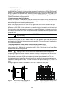
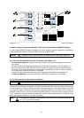
9.2.1 To Install The NRS 90207 Proceed As Follows (see diagram 9):
- for opening the appliance, please remove the 9 screws on the top of the appliance that lock the cover
plate.
- the NRS 90207 gets retrofitted on the printed board assembly 89019.1, which is located behind the input
printed board assembly 81331, in the front area, attached to the left side panel of the amplifier (in front
view).
- Be sure to first insert the included board-guides before installing the NRS 90207, assuring the correct
position of their guide grooves. The release lever of the guides marked “C” points to the top, while the
one of the guides marked “D” points downwards.
- the NRS 90207 extension-kit needs to be inserted with its printed side pointing to the top, until it firmly
locks in place. Make sure that the power resistors R917 to R920 that are located underneath the
NRS-printed board assembly do not touch this board.
- closing the appliance: use the 9 screws M3 x 6 DIN 7500 to reattach the cover plate.
30