


7.4 GROUND FAULT Indicator
If, with built-in NRS 90207 a ground fault condition at one of the power outputs occurs, the corresponding
red GROUND FAULT indicator (6) lights and a fault-message is transmitted to the PROMATRIX Manager
DPM 4000. The power amplifier keeps up normal operation during the occurrence of this fault-type. After
solving the problem, the GROUND FAULT indicator (6) can be reset by pressing the TEST button (3) or
by sending the corresponding command via the serial port of the PROMATRIX Manager DPM 4000 (see
PROMATRIX handbook) (see paragraph 9.2).
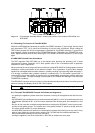
7.5 Meter Instruments And CLIP Indicators
The green LED-indicator -13 dB and 0 dB (1) as well as the red LED-indicator CLIP (2) allow the precise
monitoring of output levels, providing the possibility to securely prevent distortion and clipping that could
lead to damaging the connected loudspeaker systems.
- When during program peaks the red CLIP-LED (2) lights briefly, the maximum distortion-free output
is gained.
- Whenever the CLIP-LED (2) lights continuously, the amplifier is driven into overdrive and the input level
should be reduced.
- Overload or short-circuit at the output is the cause for the green LED-indicator (1) to be out or only briefly
lit while at the same time the red CLIP-LED (2) blinks. In that case, please check the impedance of the
connected load.
Caution During normal operation, the red CLIP-LED (2) should hardly light and if, than
only very briefly !
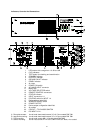
7.6 STATUS Indicator
The yellow STATUS-LED (14) that is located on the rear of the appliance lights briefly during normal
operation when the DPM 4000 addresses a query to the amplifier. For further information, please refer to
the PROMATRIX handbook.
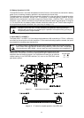
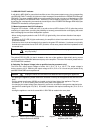
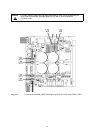
8. Switching The Output Voltage (refer to qualified service personnel only!)
The DPA 4411 offers output voltages of either 20 V, 50 V, 70 V or 100 V. The output voltage is
factory-preset to 100 V. Switching the output voltage to 20 V, 50 V or 70 V should only be carried out by
qualified DYNACORD service personnel.
Caution Unplug the mains cord and disconnect batteries before opening the appliance!
- for opening the appliance, please remove the 9 screws on the top of the appliance that lock the cover
plate.
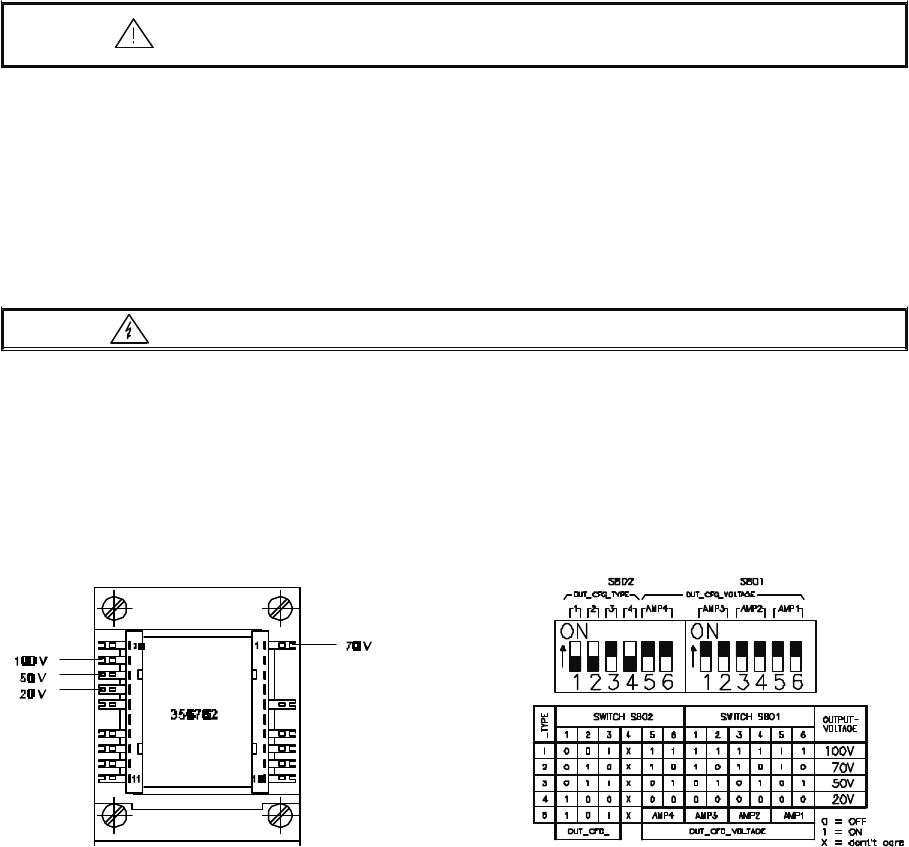
- the four output transformers 356762 are located on the left hand side of the appliance. They are
numbered 1, 2, 3, and 4; starting from the rear cover plate of the appliance.
- for changing the output voltage (see diagram 6) you have to unsolder the orange wire attached to the
transformer’s soldering tab 19 (100 V) and solder it instead to the required soldering tab (70 V, 50 V or
20 V).
- closing the appliance: use the 9 screws M3 x 6 DIN 7500 to reattach the cover plate.
diagram 6 Switching the output voltage at the
output transformers 356762
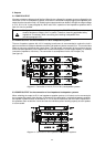
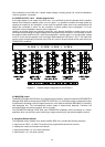
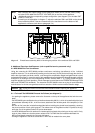
diagram 7 Output configuration settings of the
amplifiers (rear view)
28