


19
Replacing CD-ROM Drives
We have used only two manufacturers of CD-ROM drives, Toshiba and TEAC. Do not substitute with any
other manufacturer. Only drives approved by DTS will work.
Toshiba / Future Domain SCSI and the “ROM-DOS” chip
When replacing drives with ones made by Toshiba, be sure to use the current “ROM-DOS” chip. Remember
there are two types of “ROM-DOS” programmed chips available. One is for units with Future Domain SCSI
drivers. In this case, the 1Meg “ROM-DOS” programmed firmware chip used in D422-U12. The second type
is a 4Meg chip and is described below.
TEAC / Acqutek & Adaptec SCSI and the “AQRM_R” chip
The 4Meg programmed firmware chip is labeled one of two ways: The “ROMDOSB” is used for 16x drives
and has been updated to “AQRM” which must be used with 32x drives and can be used with 16x drives.
When replacing drives with TEAC, look to see what is already installed. For TEAC drives, the Adaptec SCSI
and Acqutek ROM boards are required.
TEAC 32x drives must use the “AQRM” firmware. TEAC 16x drives
should be updated to “
AQRM”.
Tools Required
Phillips head screwdriver, #2
Nut driver, 5/16”
DTS Setup Disc DS1
DTS Upgrade kit
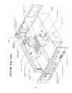
1. Turn the player’s power switch off. Remove the player from sound rack and open player’s top cover.
2. Remove all the drives from player. Removal of the player’s front panel may be required to access the drives.
Save all screws and nuts.
3. Remove SCSI board from the player. The Future Domain SCSI board must be removed. Save the
#4 mounting screw.
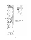
4. Remove U12 “
ROM-DOS” chip from D422 timecode board, inside the player. D422-U12 must be
removed. U12 is no longer used.
5. Remove U14 (TCR firmware chip) from D422 board and install new TCR firmware chip in its place. New
firmware chip should be labeled “V1.46”. When installing, check orientation of pin 1.
6. Install replacement drives. Carefully connect power (4-pin
MOLEX) and data (50-pin ribbon) cables.
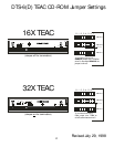
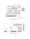
7. Address the drives for their location. Use the “DTS-6/D TEAC CD-ROM Jumper Settings” diagram.
Use the drawings to match the back panel of the given drive. Remember, only the last drive should
be terminated and all drives must be the same model. Look carefully at each drive, the address
locations do not always line up with the panel screening. The first (left) pair of terminals is always
position “0”. See next page.