


9
ENGLISH
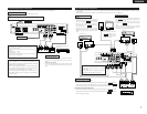
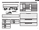
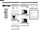
(6) Connecting to a TV or Monitor Equipped with Component Input Connectors
• When making connections, also refer to the operating instructions of the other components.
• The video signals input to the VIDEO input (yellow) and S-Video input jacks are not output to the color difference (component)
video jacks.
SPEAKER SYSTEMS
6 16
R
L
IMPEDANCE
CENTER
SURROUND
R
L
FRONT
SUB
WOOFER
IN
V.AUX
OUT
IN
TV/DBS
DIGITAL(OPTICAL)
IN OUTININ
TV/DBS
IN
V.AUX
VCR
MON.OUT
S VIDEO
IN OUTININ
TV/DBS
IN
V.AUX
VCR
MON.OUT
VIDEO
R
L
IN OUT IN ININ OUT
V.AUXTV/DBS VCR
CDR/
TAPE
PRE OUT
SUB WOOFER
AM
FM COAX. 75
LOOP ANT.
AUDIO
Y
C
B
COMPONENT VIDEO OUT
CR
COMPONENT VIDEO IN
C
B CRY
Color component output connectors (CR, CB and Y)
The red (C
R), blue (CB) and brightness (Y) signals are output independently, achieving more faithful
reproduction of the colors.
• The color component input connectors may be marked differently on some TVs or monitors (P
R, PB
and Y/R-Y, B-Y and Y/CR, CB and Y, etc.). For details, refer to the TV’s operating instructions.
Monitor TV
Connecting a monitor TV
• Connect the TV’s color difference
(component) video input jacks
(COMPONENT VIDEO INPUT) to the
COMPONENT VIDEO OUT jack using
75 Ω/ohms coaxial video pin-plug cords.
NOTES:
• Use the three commercially available video cords to connect the ADV-1000’s color component output connectors
to the TV or monitor.
• Set the “TV TYPE” in “VIDEO SETUP” in “DVD SETUP” to comply with your TV’s video format. When the TV is
PAL formated set to PAL.
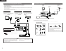
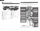
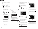
2 Selecting the type of disc for the type of connected TV
Both DVD discs and video CDs have the material recorded in the PAL and NTSC systems. Refer to the table below to select the
correct disc type for the type of connected TV.
Disc TV Monitor
PAL
Played in the PAL system.
Played in the NTSC system.
NTSC
•
Connecting to the Multi-system TV
Disc TV Monitor
PAL
No clear images are shown
on the screen.
Played in the NTSC system.
NTSC
•
Connecting to the NTSC TV
Disc TV Monitor
PAL
Played in the PAL system.
No clear images are shown
on the screen.
NTSC
•
Connecting to the PAL TV
NOTE:
When a disc which does not comply with Video CD standard is
played, the bottom part of the picture may disappear.
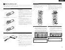
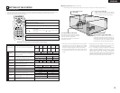
(7) Sound output from this unit digital audio output connectors
2 When a disc is played on the ADV-1000
Settings
Refer to
page
Digital audio data output
Audio recording format
DVD video
DVD audio
(video part only)
Video CD
Music CD
MP3 CD
Dolby Digital
DTS
48 kHz
96 kHz
CP : ON
CP : OFF
MPEG 1
Linear PCM
MP 3
Digital out : Normal
43
43
Dolby Digital bitstream
2 channels PCM data (48 kHz/16 bit)
DTS bitstream
DTS bitstream
48 kHz/16 ~24 bit PCM
48 kHz/16 bit PCM
48 kHz/16 bit PCM
48 kHz/16 bit PCM (when copy-protected)
96 kHz PCM (when not copy-protected)
44.1 kHz/16 bit PCM
44.1 kHz/16 bit PCM
32 ~ 48 kHz/16 bit PCM
Digital out : PCM conversion
Digital out : Normal
Digital out : PCM conversion
LPCM conversion mode : OFF
LPCM conversion mode : ON
LPCM conversion mode : ON
LPCM conversion mode : OFF
LPCM conversion mode : OFF
Linear PCM
• Linear PCM audio is the signal recording format used for music CDs.
While the signals are recorded at 44.1 kHz/16 bit for music CDs, for DVDs they are recorded at 48 kHz/16 bit to 96 kHz/24 bit,
providing higher sound quality than music CDs.
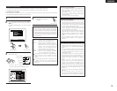
Protector circuit
• This unit is equipped with a high-speed protection circuit. The purpose of this circuit is to protect the
speakers under circumstances such as when the output of the power amplifier is inadvertently short-
circuited and a large current flows, when the temperature surrounding the unit becomes unusually high,
or when the unit is used at high output over a long period which results in an extreme temperature rise.
When the protection circuit is activated, the speaker output is cut off and the power supply indicator LED
flashes. Should this occur, please follow these steps: be sure to switch off the power of this unit, check
whether there are any faults with the wiring of the speaker cables or input cables, and wait for the unit to
cool down if it is very hot. Improve the ventilation condition around the unit and switch the power back on.
If the protection circuit is activated again even though there are no problems with the wiring or the
ventilation around the unit, switch off the power and contact a DENON service center.
Note on speaker impedance
• The protector circuit may be activated if the set is played for long periods of time at high volumes when
speakers with an impedance lower than the specified impedance (for example speakers with an
impedance of lower than 4 Ω/ohms) are connected. If the protector circuit is activated, the speaker output
is cut off. Turn off the set’s power, wait for the set to cool down, improve the ventilation around the set,
then turn the power back on.
Cautions on connecting
• With this unit’s speaker outputs, signals with the reverse phase of the “+” side output terminal’s signals
are also output from the “-” side output terminal.
Do not connect to a device for switching between multiple speakers (a speaker selector or audio channel
selector) or connect in ways other than described in this manual. Doing so will result in damage.