


7
ENGLISH
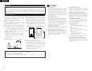
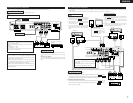
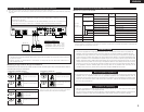
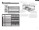
(2) Connecting the audio components
• When making connections, also refer to the operating instructions of the other components.
Connecting the DIGITAL (optical) jacks
Use these for connections to audio equipment with digital (optical) output.
NOTE:
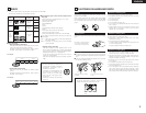
• Use optical cables for optical connections, removing the cap before connecting.
SPEAKER SYSTEMS
6 16
R
L
IMPEDANCE
CENTER
SURROUND
R
L
FRONT
SUB
WOOFER
IN
V.AUX
OUT
IN
TV/DBS
DIGITAL(OPTICAL)
IN OUTININ
TV/DBS
IN
V.AUX
VCR
MON.OUT
S VIDEO
IN OUTININ
TV/DBS
IN
V.AUX
VCR
MON.OUT
VIDEO
R
L
IN OUT IN ININ OUT
V.AUXTV/DBS VCR
CDR/
TAPE
PRE OUT
SUB WOOFER
AM
FM COAX. 75
LOOP ANT.
AUDIO
Y
C
B
COMPONENT VIDEO OUT
CR
OPTICAL
IN
OUTPUT
L
R
INPUT
LR
L
R
R
L
L
R
L
R
B
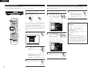
Subwoofer jack
Connect the internal amplifier’s subwoofer to
the subwoofer terminal.
•
To conduct digital recording onto a digital recorder (CD recorder,
MD recorder, etc.) while playing Dolby Digital, 96 kHz PCM
sources on this DVD player.
•
Set the “AUDIO SETUP” default setting as shown below. (See
page 43.)
• “DIGITAL OUT” → “PCM”
“LPCM SELECT” → “ON”
Playing DVDs with incorrect settings may result noise that could
damage your ears or the speakers.
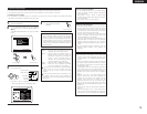
NOTES:
• Track numbers may not be added automatically when
making digital recordings of CDs being played on the ADV-
1000 onto a connected recorder.
• When making digital recordings on a CD recorder, set the
CD recorder’s recording setting to manual and add track
numbers (track marks) manually as you record.
• When making digital recordings on an MD recorder, use
the editing function after the recording is completed to
divide the tracks.
AC CORD
AC 230 V, 50 Hz
CD recorder, MD recorder or
Tape deck
Connecting a recorder
Connections for recording:
Connect the tape deck’s recording input jacks (LINE IN or REC) to
this unit’s tape recording (CDR/TAPE OUT) jacks using pin plug
cords.
Connections for playback:
Connect the tape deck’s playback output jacks (LINE OUT or PB)
to this unit’s tape playback (CDR/TAPE IN) jacks using pin plug
cords.
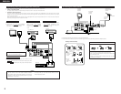
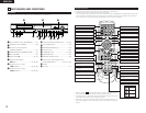
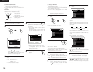
(3) Connecting video components
• To connect the video signal, connect using a 75 Ω/ohms video signal cable cord. Using an improper cable can result in a drop in
video quality.
• When making connections, also refer to the operating instructions of the other components.
IN
V.AUX
OUT
IN
TV/DBS
DIGITAL(OPTICAL)
IN OUTININ
TV/DBS
IN
V.AUX
VCR
MON.OUT
S VIDEO
IN OUTININ
TV/DBS
IN
V.AUX
VCR
MON.OUT
VIDEO
R
L
IN OUT IN ININ OUT
V.AUXTV/DBS VCR
CDR/
TAPE
PRE OUT
SUB WOOFER
AM
FM COAX. 75
LOOP ANT.
AUDIO
Y
C
B
COMPONENT VIDEO OUT
CR
VIDEO
OUT
AUDIO
OUT
L
R
VIDEO
OUT
INLR
OUT IN
L
R
AUDIO
OUT
OPTICAL
VIDEO
OUT
AUDIO
OUT
L
R
OUT
OPTICAL
VIDEO
IN
L
R
R
L
R
L
L
R
L
R
L
R
B
B
L
R
R
L
Connecting a TV/DBS tuner
TV/DBS
• Connect the TV’s or DBS tuner’s video output jack
(VIDEO OUTPUT) to the (yellow) TV/DBS IN
jack using a 75 Ω/ohms video coaxial pin plug cord.
• Connect the TV’s or DBS tuner’s audio output jacks
(AUDIO OUTPUT) to the TV/DBS IN jacks
using pin plug cords.
• For devices with optical digital outputs, connect the
digital output terminal to the ADV-1000’s DIGITAL
TV/DBS IN terminal using an optical transmission
cable.
AUDIO
VIDEO
TV or DBS tuner
Monitor TV
MONITOR OUT
• Connect the TV’s video input
jack (VIDEO INPUT) to the
MONITOR OUT jack
using a 75 Ω/ohms video
coaxial pin plug cord.
VIDEO
Connecting a CS tuner
V.AUX
• Connect the CS tuner’s video output jack (VIDEO OUTPUT)
to the (yellow) V.AUX IN jack using a 75 Ω/ohms
video coaxial pin plug cord.
• Connect the CS tuner’s audio output jacks (AUDIO
OUTPUT) to the V.AUX IN jacks using pin plug
cords.
• For devices with optical digital outputs, connect the digital
output terminal to the ADV-1000’s DIGITAL V.AUX. IN
terminal using an optical transmission cable.
AUDIO
VIDEO
CS tuner
Video deck
Note on connecting the digital input jacks
• Only audio signals are input to the digital
input jacks.
• Use optical cables for optical connections,
removing the cap before connecting.
Video input/output connections:
• Connect the video deck’s video output jack (VIDEO OUT) to the (yellow)
VCR IN jack, and the video deck’s video input jack (VIDEO IN) to the
(yellow) VCR OUT jack using 75 Ω/ohms video coaxial pin plug cords.
Connecting the audio output jacks
• Connect the video deck’s audio output jacks (AUDIO OUT) to the VCR IN
jacks, and the video deck’s audio input jacks (AUDIO IN) to the VCR OUT
jacks using pin plug cords.
AUDIO
AUDIO
VIDEO
VIDEO
Connecting a video decks