


Connections Setup Playback Remote Control Multi-Zone Information Troubleshooting
ENGLISH
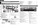
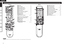
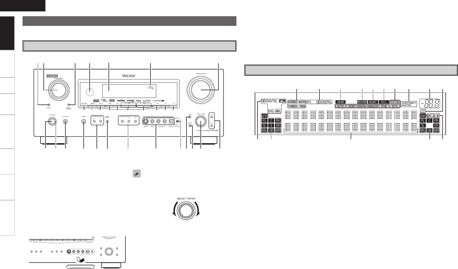
For buttons not explained here, see the page indicated in parentheses ( ).
q w e r
W1 W2 W3 W4 W5 W6 W7 W8 W9 E0
y u i oQ0Q1 Q2 Q3t
Q4Q5Q6Q7Q8Q9W0
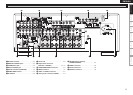
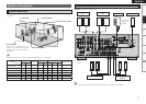
q Power operation button
(ON/STANDBY) ···········································(43)
w Power indicator ···········································(43)
e Power switch (hON jOFF) ·····················(43)
r Headphones jack (PHONES) ······················(43)
t SPEAKER buttons ·······································(43)
y ZONE2 ON/OFF button ······························(58)
u QUICK SELECT buttons ·····························(50)
i V. AUX INPUT connectors
Remove the cap covering the terminals when
you want to use them.
o SETUP MIC jack ··········································(22)
Q0 MENU button ··············································(19)
Q1 RETURN button ·········································· (19)
Q2 SELECT/ENTER knob ································· (19)
u yiQ4Q5 oQ0Q1Q2Q3
wq e r t
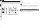
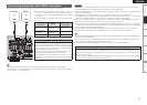
q Input signal indicators
w Input signal channel indicators
These light when digital signals are input.
e Information display
The input source name, surround mode, setting
values and other information are displayed here.
r Output signal channel indicators
t Front speaker indicators
These light according to the settings of the front
A and B speakers.
y ZONE2 output indicator
This lights when the power for the ZONE2 is
turned on.
u Master volume indicator
i AUDYSSEY MULTEQ indicator
This lights when the room equalizer is selected.
o Input mode indicators
Q0 Recording output source indicator
This lights when the REC OUT mode is
selected.
Q1 NIGHT indicator
This lights when the night mode is selected.
Q2 RESTORER indicator
This lights when the RESTORER mode is
selected.
Q3 HDMI indicator
This lights when playing using HDMI
connections.
Q4 Decoder indicators
These light when the respective decoders are
operating.
Q5 Tuner reception mode indicators
These light according to the reception conditions
when the input source is set to “TUNER”.
• AUTO
This lights when in the auto tuning mode.
• RDS
This lights when receiving RDS broadcasts.
• STEREO
In the FM mode, this lights when receiving
analog stereo broadcasts.
• TUNED
This lights when the broadcast is properly tuned
in.
Part Names and Functions
Front Panel
Display
• The SELECT/ENTER knob on the main unit operates
in the same way as the CURSOR o and p buttons
on the remote control unit.
• The control functions in the same way as the
CURSOR o button when turned counterclockwise,
as the CURSOR p button when turned clockwise.
• The control functions in the same way as the
ENTER button when pressed the knob.
W5 SHIFT button ···············································(45)
W6 PRESET buttons ··········································(45)
W7 TUNING buttons ·········································(44)
W8 RDS button ··················································(46)
W9 PTY button ··················································(46)
E0 RT button ····················································(47)
Q3 Cursor buttons (ui) ································· (19)
Q4 MASTER VOLUME control knob ················(43)
Q5 Master volume indicator
Q6 Display
Q7 Remote control sensor ·································(3)
Q8 ZONE2/REC SELECT button ······················(49)
Q9 SOURCE SELECT knob·······························(43)
W0 SOURCE button ··········································(43)
W1 INPUT MODE button ··································(34)
W2 ANALOG button ··········································(34)
W3 EXT. IN button ·············································(34)
W4 BAND button ···············································(44)
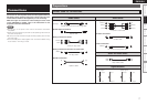
Getting Started